
Transmitter method for supporting a determination of a set of beamforming weights by a receiver method, receiver method, transmitter apparatus, receiver apparatus and network node thereof

A beamforming and transmitter technology, applied in the field of determining beamforming weight sets, can solve problems such as unfavorable operation and long experiments, and achieve the effects of a flexible mechanism, a fast adaptive, and reliable mechanism

Inactive Publication Date: 2016-06-15
ALCATEL LUCENT SAS
View PDF3 Cites 14 Cited by
  • Summary
  • Abstract
  • Description
  • Claims
  • Application Information

AI Technical Summary

Problems solved by technology

The disadvantage of this method is the relatively long trial and error phase, since for each direction at the transmitter all possible receiver directions need to be scanned
Therefore, this method is suitable for channel investigation, but is very unfavorable for the operation of flexible and dynamic communication systems

Method used


Image

  • Transmitter method for supporting a determination of a set of beamforming weights by a receiver method, receiver method, transmitter apparatus, receiver apparatus and network node thereof
  • Transmitter method for supporting a determination of a set of beamforming weights by a receiver method, receiver method, transmitter apparatus, receiver apparatus and network node thereof
  • Transmitter method for supporting a determination of a set of beamforming weights by a receiver method, receiver method, transmitter apparatus, receiver apparatus and network node thereof

Examples


Embodiment Construction

[0030] The description and drawings merely illustrate the principles of the invention. It will thus be appreciated that those skilled in the art will be able to devise various arrangements which, although not explicitly described or shown, embody the principles of the invention and are included within its spirit and scope. Furthermore, all examples set forth herein are primarily intended to be expressly for instructional purposes only to assist the reader in understanding the principles of the invention and the inventor's contribution to the advancement of the state of the art, and should be construed as not limiting to those specifically recited Examples and conditions. Moreover, all statements herein reciting principles, aspects, and embodiments of the invention, as well as specific examples thereof, are intended to encompass equivalents thereof.

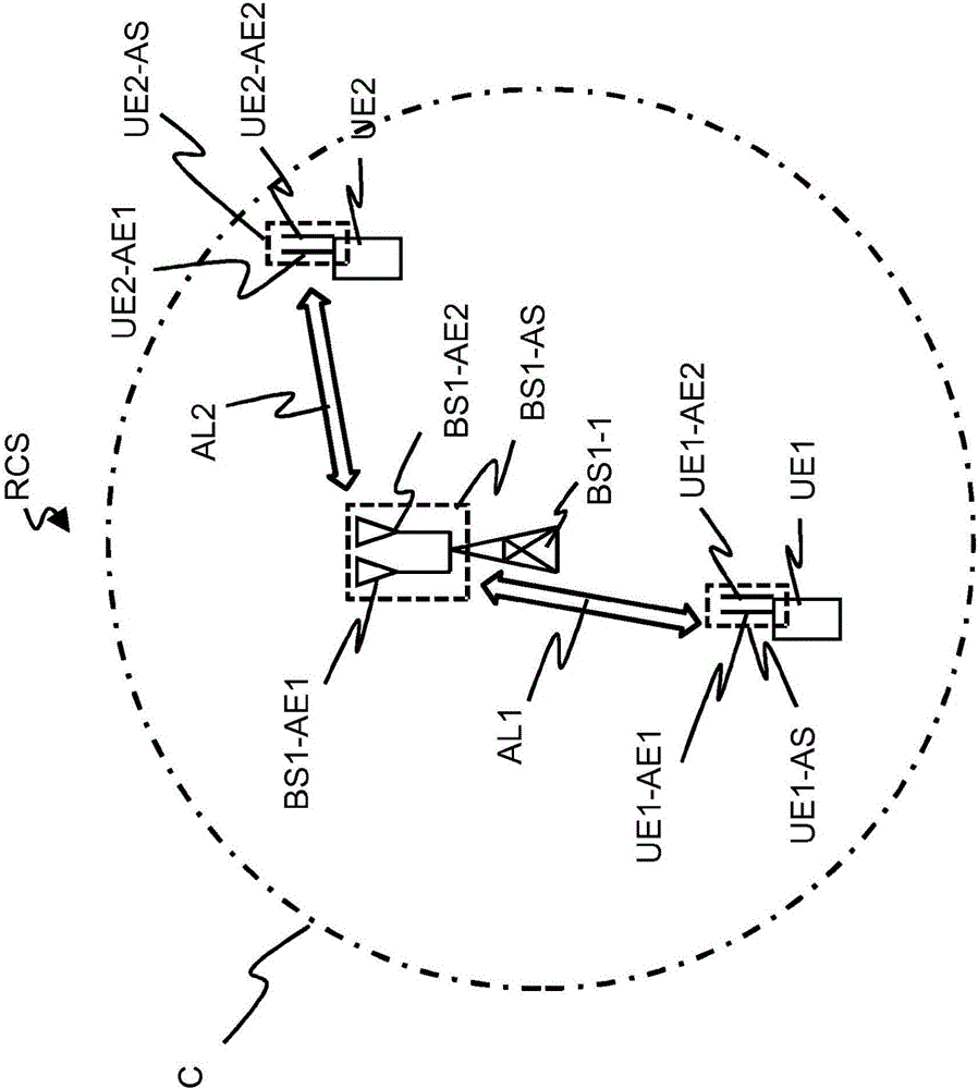
[0031] figure 1 A radio communication system RCS with a first application scenario of an embodiment of the present invention i...


PUM


Abstract

The embodiments of the invention relate to a transmitter method for supporting a determination of a set of beamforming weights by a receiver method. The transmitter method contains the steps of allocating a predefined reference signal (REF-SIG-1a, REF-SIG-2a) to at least one group of radio resource units (RRU-G1a, RRU-G2a) of a transmission channel between a first antenna array and a second antenna array, and transmitting said predefined reference signal (REF-SIG-1a, REF-SIG-2a) via the transmission channel from the first antenna array to the second antenna array. The embodiments of the invention further relate to a receiver method for a determination of a set of beamforming weights. The receiver method contains the steps of receiving at a first antenna element of a second antenna array and at least one further antenna element of the second antenna array via a transmission channel from a first antenna array a predefined reference signal (REF-SIG-1a, REF-SIG-2a) allocated to at least one group of radio resource units(RRU-G1a, RRU-G2a) of the transmission channel, determining based on the received predefined reference signal (REF-SIG-1a, REF-SIG-2a)a first channel estimation of the transmission channel for the first antenna element and at least one further channel estimation of the transmission channel for the at least one further antenna element, and determining the set of beamforming weights for a transmission from the second antenna array and / or a reception at the second antenna array based on the first channel estimation and the at least one further channel estimation. The embodiments of the invention even further relate to a transmitter apparatus, a receiver apparatus and a network node, which contains a transmitter apparatus and a receiver apparatus.

Description

technical field [0001] The present invention relates to radio transmission via a plurality of antenna elements, and more particularly, but not exclusively, to the determination of a set of beamforming weights for transmitting and / or receiving millimeter waves through a large number of antenna elements of an antenna array. Background technique [0002] This section introduces aspects that may help to facilitate a better understanding of the invention. Accordingly, the statements in this section are read in this regard, and should not be construed as an admission that there is something in the prior art. [0003] To estimate beamforming weights for an antenna array, channel estimation is typically performed independently for each antenna element. Based on the channel estimate, the beamforming weights are then calculated using a suitable algorithm, eg the well known MRC algorithm (MRC = Maximum Ratio Combining) to maximize the received power. [0004] When using mm waves (mm=...

Claims


Application Information

Patent Timeline
Patent Type & Authority Applications(China)
IPC IPC(8): H04B7/06H04B7/04H04L5/00
CPCH04B7/0413H04B7/0617H04L27/2613H04L5/0048H04B7/0404H04B7/0848H04L25/0202H04L27/26132
Inventor H·哈尔鲍尔F·博卡迪
Owner ALCATEL LUCENT SAS
Learn More