Driving circuit, organic light-emitting diode display and driving method

A technology for driving circuits and light-emitting units, applied in static indicators, instruments, etc., can solve the problems of uneven brightness, different threshold voltages, and insufficient potential of N1 node, so as to avoid uneven brightness, improve dark state effects, Avoid the effect of luminous current differences

Active Publication Date: 2016-06-15
WUHAN TIANMA MICRO ELECTRONICS CO LTD +1
View PDF6 Cites 17 Cited by
  • Summary
  • Abstract
  • Description
  • Claims
  • Application Information

AI Technical Summary

Problems solved by technology

However, due to the threshold drift of transistors in the manufacturing process, that is to say, the threshold voltages of any two transistors are not exactly the same
Therefore, using figure 1 The display panel of the pixel circuit shown is prone to the problem of uneven brightness during the display process
[0011] 3) Due to the capacitance C st (does not correspond to the figure) coupling effect, such as figure 2 As shown, when the rising edge of the S2 signal arrives (such as figure 2 Indicated by the reference numeral 210), the potential of the N1 node is pulled up, and when the falling edge of the Emit signal arrives (as figure 2 Indicated by reference numeral 220), the N1 node drops accordingly (as figure 2 Indicated by the reference numeral 230 in the middle), in this way, due to the coupling of the capacitor C1, the potential of the N1 node is not high enough, which may lead to the use of figure 1 The dark state of the display panel of the pixel circuit shown is not dark, which makes the display effect of the dark state of the display panel poor

Method used


Image

  • Driving circuit, organic light-emitting diode display and driving method
  • Driving circuit, organic light-emitting diode display and driving method
  • Driving circuit, organic light-emitting diode display and driving method

Examples


Embodiment Construction

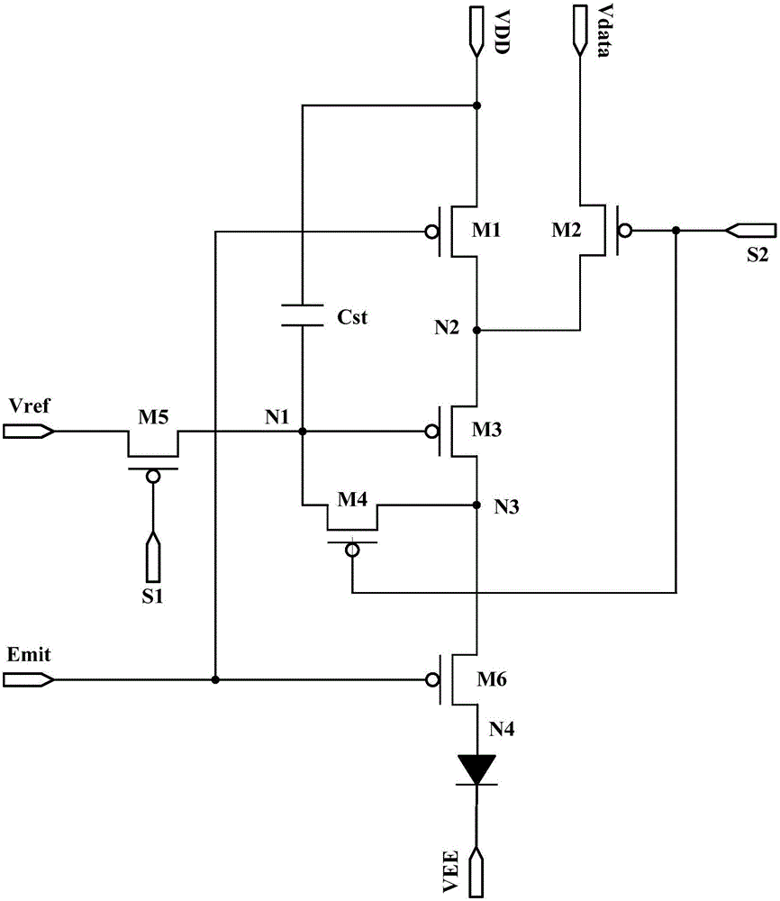
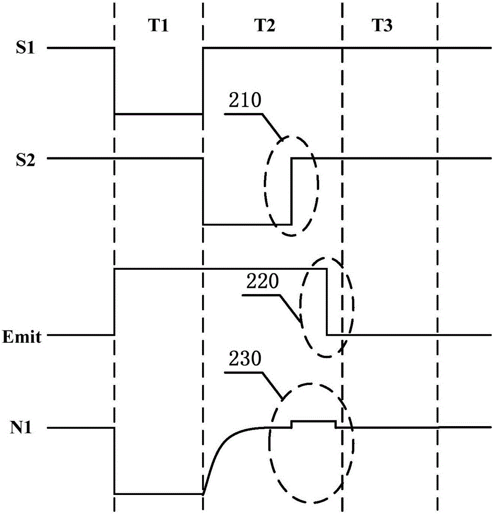
[0027] The application will be further described in detail below in conjunction with the accompanying drawings and embodiments. It should be understood that the specific embodiments described here are only used to explain related inventions, rather than to limit the invention. It should also be noted that, for ease of description, only parts related to the invention are shown in the drawings.

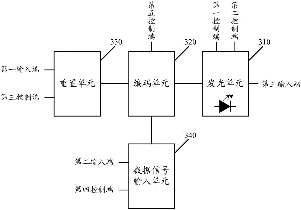
[0028] see image 3 Shown is a schematic structural diagram of an embodiment of the driving circuit of the present application.

[0029] The driving circuit of this embodiment includes at least one driving module. image 3 It schematically shows that the driving circuit includes a driving module.

[0030] The drive module includes a light emitting unit 310, an encoding unit 320, a reset unit 330 and a data signal input unit 340;

[0031] in:

[0032] The light emitting unit 310 includes a first control terminal, a second control terminal and a light emitting diode.

[0033] The re...


PUM


Abstract

The invention discloses a driving circuit, an organic light-emitting diode display device and a driving method. The driving circuit comprises at least one driving module; each driving module includes a light-emitting unit, a coding unit, a reset unit and a data signal input unit; the reset unit is used for providing reset signals to the coding unit; the data signal input unit is used for providing data signals inputted by a second input end to the coding unit; and the coding unit is used for receiving and compensating first voltage signals received by a third input end of the light-emitting unit, generating light emission control signals based on the data signals and providing the light emission control signals to the light-emitting unit, wherein the light emission control signals are unrelated to the first voltage signals. With the driving circuit, the organic light-emitting diode display and the driving method provided by the embodiments of the invention adopted, light emission current difference caused by the potential difference of first voltage signals which is further caused by distance difference of driving circuits at different areas of a display panel and ICs can be avoided, and therefore, the problem of the unevenness of the brightness of the different areas of the display panel can be solved.

Description

technical field [0001] The present disclosure generally relates to display technology, and more particularly, to a driving circuit, an OLED display and a driving method. Background technique [0002] With the continuous development of display technology, the sizes and specifications of displays are changing with each passing day. For example, in order to meet the portability of electronic devices, the demand for smaller size display screens continues to increase. [0003] In addition, with the development of display technology, users have higher requirements on the display quality of the display screen. For example, users tend to prefer high PPI (PixelperInch, pixels per inch) display screens to improve display accuracy and coherence. The OLED (Organic Light-Emitting Diode, Organic Light-Emitting Diode) display is more and more widely used in various portable electronic devices because of its thinness, power saving and other characteristics. [0004] An OLED display gener...

Claims


Application Information

Patent Timeline
IPC IPC(8): G09G3/3258
CPCG09G3/3258
Inventor 钱栋彭冠臻李玥邹文晖
Owner WUHAN TIANMA MICRO ELECTRONICS CO LTD
Why Eureka
Try Eureka