
Method for analyzing crosstalk of transmission lines in any layout

An analysis method and technology of arbitrary layout, applied in the field of signal transmission, can solve the problem of less analysis of crosstalk of transmission lines with arbitrary layout

Inactive Publication Date: 2016-06-15
SHENYANG AEROSPACE UNIVERSITY
View PDF3 Cites 7 Cited by
  • Summary
  • Abstract
  • Description
  • Claims
  • Application Information

AI Technical Summary

Problems solved by technology

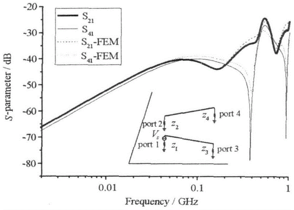
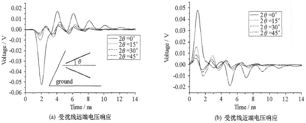
In actual circuits or wiring, the situation of non-parallel lines is unavoidable. For example, the cable layout of automobiles, airplanes and ships will change direction with the change of shape. The existing technology only involves the crosstalk of parallel lines. analysis, less analysis of crosstalk between arbitrary layout transmission lines

Method used


Image

  • Method for analyzing crosstalk of transmission lines in any layout
  • Method for analyzing crosstalk of transmission lines in any layout
  • Method for analyzing crosstalk of transmission lines in any layout

Examples


Embodiment 1

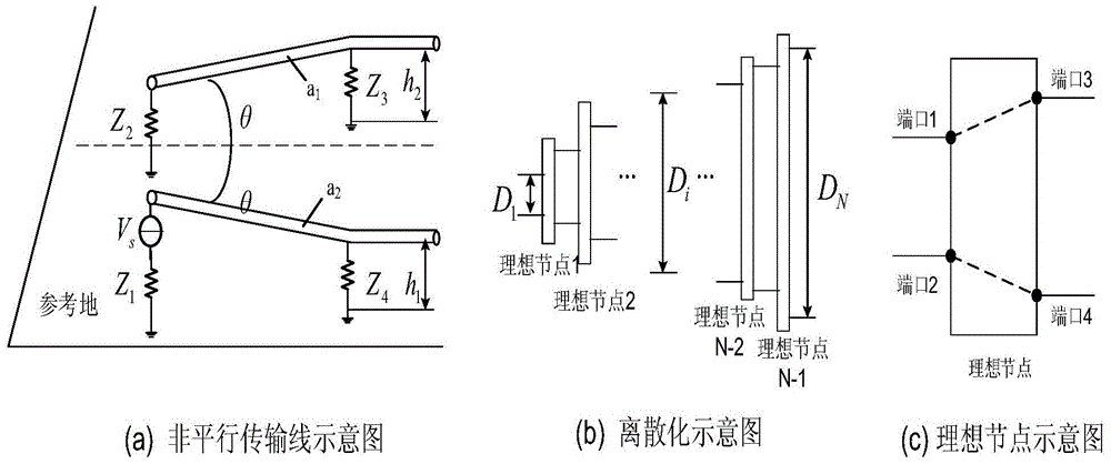
[0027] If it is judged as a non-parallel transmission line:

[0028] The traditional BLT equation can only deal with the case of consistent transmission lines. Therefore, to use the BLT equation to solve the crosstalk of arbitrarily placed transmission lines, it is necessary to discretize the transmission lines. Each discrete line segment is approximately regarded as a coherent transmission line.

[0029] consider as figure 1 In the situation shown in (a), the reference ground can be ideal or lossy. It is the two transmission lines of the common circuit, and the height from the ground is h 1 , h 2 , the line radius is a 1 a 2 , the two lines are not parallel, and the angle between them is 2θ.

[0030] figure 1 (b) is the discretization schematic diagram of non-parallel transmission lines, the distance between the near ends of the two lines is D 1 , far away from D N , the line length is L. If the line is discretized into N segments, then the spacing of the i segment ...

Embodiment 2

[0044] If it is judged to be a cross transmission line:

[0045] Crossing lines are different from ordinary non-parallel lines. Mutual coupling does not have to be considered for the entire line. This is because the coupling in the area beyond a certain distance from the intersection point is extremely small, and a coupling area can be determined to describe it. In the area, it is regarded as a non-parallel multi-conductor transmission line, and the processing method is the same as that of a non-parallel transmission line; outside the area, mutual coupling is not considered. It should be noted that the port connection status of node 0 is opposite to that of other nodes. Such as Figure 4 As shown, let the angle between the two lines projected on the ground plane be θ, and the intersection point be z 1 =z 2 = 0 points. Determine a convergence criterion R, let the unit length mutual inductance of two lines at the intersection point be M 0 ,|z 1 |=|z 2 |=The unit length mu...


PUM


Abstract

The invention aims at providing a method for analyzing crosstalk of transmission lines in any layout, and the transmission lines are not parallel and are crossed. The method specifically comprises the following steps that firstly, the type of transmission line layout is judged, if the transmission lines are not parallel, a third step is executed, and if the transmission lines are crossed, a second step is executed; secondly, a coupled region and an uncoupled region of the crossed transmission lines are judged, if it is judged as the coupled region, the third step is executed, and if it is judged as the uncoupled region, cross coupling influences are not taken into consideration; thirdly, nodes are introduced to connecting points of dispersing segments and are named as ideal nodes, and scattering parameters of all the nodes and transmission functions of all the dispersing segments are solved; fourthly, the results obtained in the third step are substituted into a BLT equation, voltages of all the nodes can be obtained, and then the crosstalk among the lines is obtained.

Description

technical field [0001] The invention belongs to the technical field of signal transmission, and in particular relates to an analysis method for crosstalk of arbitrary layout transmission lines. Background technique [0002] In electromagnetic compatibility issues, transmission lines refer to connecting wires in all electronic devices and equipment. In electrical equipment and electronic instruments, because there are many internal connecting wires, they are bundled for easy maintenance, but this will cause coupling induction between the wires, which will seriously interfere with the equipment, resulting in performance degradation or function unusual. [0003] Coupling interference between conductors in cables is one of the most common interference coupling modes in electrical engineering. Whether it is the electromagnetic compatibility problem of the electronic system or the signal integrity problem on the PCB board, the crosstalk between cables cannot be ignored. In actu...

Claims


Application Information

Patent Timeline
IPC IPC(8): G06F17/50
CPCG06F30/00
Inventor 李轩关庆阳张少卿朱文青赵丽
Owner SHENYANG AEROSPACE UNIVERSITY
Learn More