
A plasma source emission array based on microporous electrode structure

A technology of plasma and microporous electrodes, which is used in seismology in areas covered by water, can solve the problems of short electrode life, achieve long electrode life, improve electro-acoustic efficiency, and large bubble size.

Active Publication Date: 2017-12-12
ZHEJIANG UNIV
View PDF9 Cites 0 Cited by
  • Summary
  • Abstract
  • Description
  • Claims
  • Application Information

AI Technical Summary

Problems solved by technology

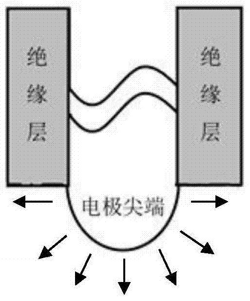
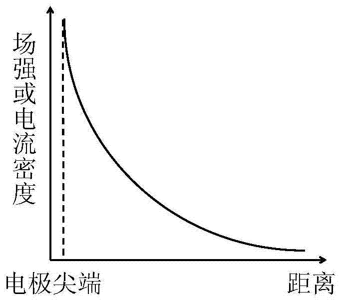
However, it is impossible to choose an infinitely small electrode radius in practical applications, and it is also necessary to take into account the strength and life of the electrode. The thinner the electrode, the shorter the life. Therefore, reducing the electrode radius is not the most effective way to improve the electroacoustic efficiency.

Method used


Image

  • A plasma source emission array based on microporous electrode structure
  • A plasma source emission array based on microporous electrode structure
  • A plasma source emission array based on microporous electrode structure

Examples


Embodiment Construction

[0036] In order to describe the present invention more specifically, the technical solutions of the present invention will be described in detail below in conjunction with the accompanying drawings and specific embodiments.

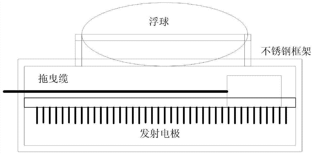
[0037] Figure 3, Figure 4 and Figure 5 These are three implementation modes of the present invention corresponding to the planar emission array, the cylindrical emission array and the spherical emission array. What all three structures have in common is that a porous insulating layer covers the high-voltage electrode and isolates it from the low-voltage electrode.

[0038]As shown in FIG. 3 , the planar emitting array is composed of a flat metal electrode 1 connected to a high voltage, a porous insulating layer 2 and a metal frame 3 connected to a low voltage, wherein the flat metal electrode 1 is embedded in the porous insulating layer 2 . The porous insulating layer 2 is divided into upper and lower parts according to the structure. The upper part is t...


PUM

PropertyMeasurementUnit
pore sizeaaaaaaaaaa
electrical conductivityaaaaaaaaaa
diameteraaaaaaaaaa

Abstract

The invention discloses a plasma source emission array based on a microporous electrode structure, comprising: a metal electrode D1 connected to a high voltage, a metal electrode D2 connected to a low voltage, and an insulating medium with a porous structure; the metal electrode D1 and the metal electrode D2 are insulated The medium is isolated, and the metal electrode D1 is only exposed to water through the micropores on the insulating medium. In the present invention, the contact between the high-voltage electrode part and the water body is realized through a micropore on an insulating layer. If the micropore diameter is small enough and the electric field and current density distribution in the micropore is uniform, the time for heating the water body will be shortened, and when the bubbles are generated It can still maintain a high field strength and can stimulate the plasma discharge in the bubble; and because the insulating layer has a certain strength, the bubble can accumulate more internal energy, thereby forming a stronger sound pressure and a larger bubble size. Therefore, the present invention can effectively improve the electro-acoustic efficiency, and at the same time, can effectively suppress the bubble pulse through reasonable micropore position arrangement.

Description

technical field [0001] The invention belongs to the field of plasma seismic source technology, and in particular relates to a plasma seismic source emission array based on a microporous electrode structure. Background technique [0002] Based on high-voltage pulse discharge technology in water, spark source or plasma source has been successfully applied in marine high-resolution seismic exploration, which mainly includes three parts: high-voltage pulse power supply, pulse transmission line and electrode emission array. The emitter electrode structure adopted by the current electric spark source or plasma source mainly includes electrode pairs, multi-electrode emitter arrays, etc. The electrode pair is suitable for pulsed arc discharge, with high electro-acoustic efficiency. Since the water body between the electrode pair needs to be broken down, the required voltage level is high. During the discharge process, an arc channel connecting the two electrode tips is generated, an...

Claims


Application Information

Patent Timeline
Patent Type & Authority Patents(China)
IPC IPC(8): G01V1/38
CPCG01V1/38G01V1/157
Inventor 张连成黄逸凡刘振闫克平
Owner ZHEJIANG UNIV
Learn More