
Interference order-based high-birefringence optical fiber beat-length measuring method and measuring device

A technology of high birefringence optical fiber and birefringent optical fiber, which is used in measurement devices, optical instrument testing, machine/structural component testing, etc. problems, to achieve the effect of improving accuracy, less influencing factors, and easy to achieve

Inactive Publication Date: 2016-06-15
ANHUI UNIVERSITY
View PDF5 Cites 4 Cited by
  • Summary
  • Abstract
  • Description
  • Claims
  • Application Information

AI Technical Summary

Problems solved by technology

In this patent, it seems that the beat length calculation error comes from the data fitting result and birefringence calculation, but in fact it still comes from the error of spectral reading and fiber length measurement, and the fitting and averaging process can only be reduced to a certain extent. The influence of measurement error cannot eliminate the error in the measurement parameters
[0006] In the above two calculation methods, the beat length calculation results depend on many measurement parameters, and each parameter has a certain measurement error, resulting in large calculation results and low measurement accuracy.

Method used


Image

  • Interference order-based high-birefringence optical fiber beat-length measuring method and measuring device
  • Interference order-based high-birefringence optical fiber beat-length measuring method and measuring device
  • Interference order-based high-birefringence optical fiber beat-length measuring method and measuring device

Examples


Embodiment Construction

[0032] combine figure 1 , which describes a specific embodiment of the present invention in detail, but does not limit the claims of the present invention in any way.

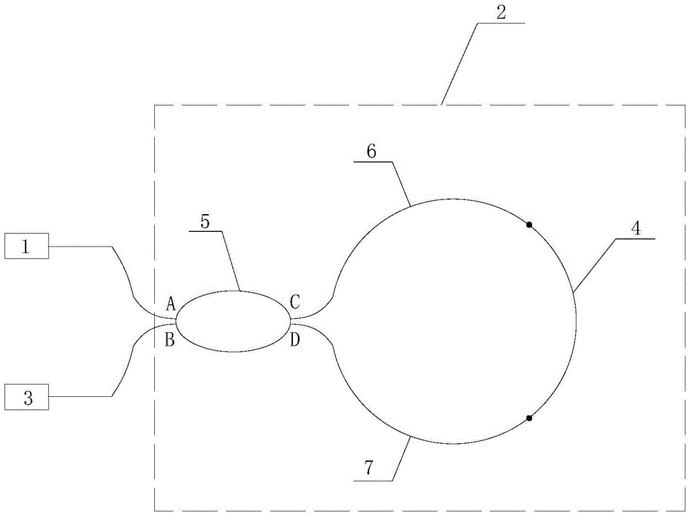
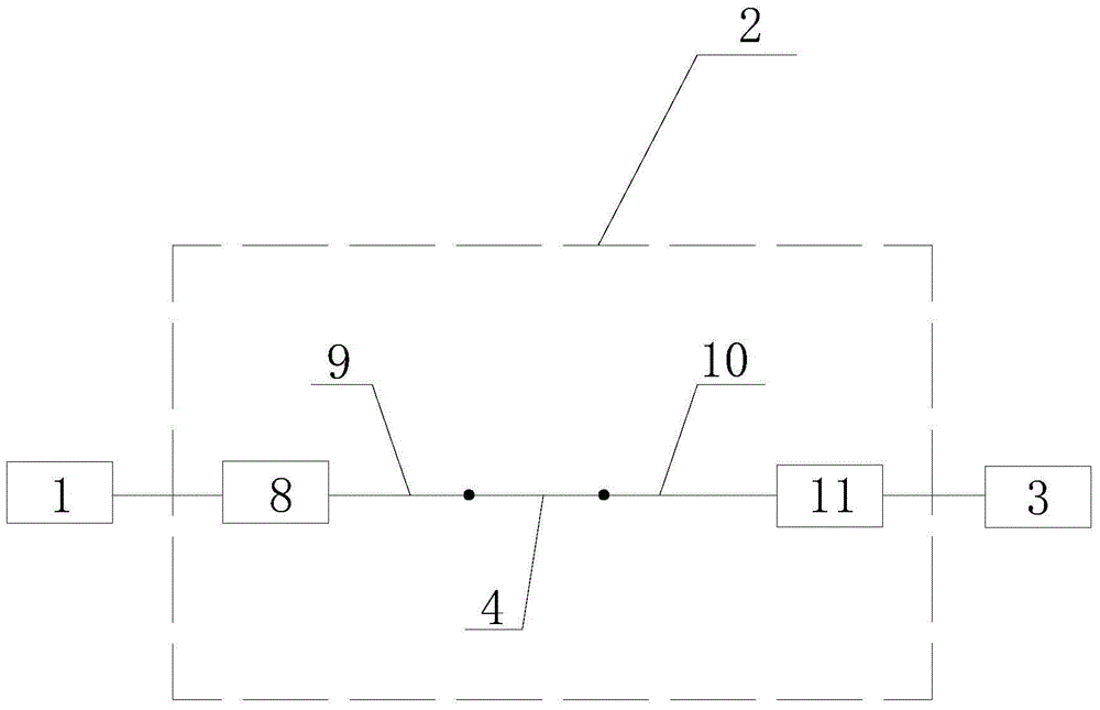
[0033] Such as figure 1 As shown, a high birefringence optical fiber beat length measurement device includes a light source 1, an interferometer 2 that uses the fast axis and slow axis of the high birefringent optical fiber to be measured to form the phase difference of the interference optical path, a spectrometer 3 and is used to measure the high birefringence optical fiber to be measured The measuring device for the length of the refracting optical fiber 4, the input end of the interferometer 2 is connected with the light source 1, and the output end is connected with the spectrometer 3.

[0034] Wherein the interferometer 2 adopts a Sagnac ring structure, and the Sagnac ring structure includes a high birefringence fiber 4 to be measured, a coupler 5, a first single-mode fiber 6 and a second single-mode fib...


PUM


Abstract

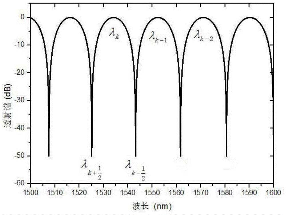
The invention relates to the field of high-birefringence optical fiber parameter measurement, and particularly provides an interference order-based high-birefringence optical fiber beat-length measuring method and a measuring device. The calculation result of an existing beat-length measuring method is dependent on multiple measurement parameters, so that the calculation result of the existing beat-length measuring method is large in error. In order to solve the above problem, the invention provides the interference order-based high-birefringence optical fiber beat-length measuring method and the measuring device. The measuring method comprises the steps of A, measuring the length L of a to-be-measured high-birefringence optical fiber; B, constructing an interferometer, wherein the fast axis and the slow axis of the high-birefringence optical fiber form the phase difference of the interference light path of the interferometer; C, obtaining an interference spectrum, acquiring the wavelengths of two adjacent extreme values and calculating an interference order N corresponding to the wavelengths of the extreme values; D, according to a beat-length calculation formula, calculating the beat lengths of the wavelengths of different extreme values. The above measuring method is dependent on fewer parameters, small in measurement error and high in measurement accuracy. The measuring device is simple in structure and easy to implement.

Description

technical field [0001] The invention relates to the field of high birefringence optical fiber parameter measurement, in particular to a method and a measuring device for measuring the beat length of a high birefringent optical fiber based on interference series. Background technique [0002] Beat length is an important parameter to characterize the characteristics of high birefringence fiber, and it needs to be measured accurately. Traditional measurement methods of high birefringence optical fiber beat length include Rayleigh scattering method, dynamic pressure method, magneto-optic modulation method, white light interferometry and interference spectroscopy. Among them, the interference spectroscopy method is to couple a wide-spectrum light source into a high birefringence fiber, and obtain the interference signal between the orthogonal polarization modes of the high birefringence fiber through a spectrometer. The wavelength interval and high birefringence fiber length can...

Claims


Application Information

Patent Timeline
Patent Type & Authority Applications(China)
IPC IPC(8): G01M11/00
CPCG01M11/331
Inventor 朱军俞本立曹志刚汪辉甄胜来
Owner ANHUI UNIVERSITY
Learn More