
Concrete strainmeter subassembly and installation method

A strain gauge and concrete technology, applied in the direction of measuring devices, instruments, etc., can solve the problems of being easily disturbed, the position is easy to change, and the measured value is easily affected by the strain of fixed steel bars, so as to achieve the effect of reducing interference

Inactive Publication Date: 2016-06-15
SOUTHWEST JIAOTONG UNIV
View PDF7 Cites 7 Cited by
  • Summary
  • Abstract
  • Description
  • Claims
  • Application Information

AI Technical Summary

Problems solved by technology

[0004] The way here is in actual engineering, when placing the concrete strain gauge, on the one hand, because the concrete strain gauge has no force point, it is easily disturbed when the concrete is poured or sprayed, and the position is easy to change, thus making the strain measured by the concrete strain gauge invalid , the accuracy and reliability of the monitoring data cannot be guaranteed; on the other hand, when the concrete strain gauge is bound to the fixed steel bar, the concrete strain gauge and the shotcrete The contact is not dense, and the measured value is easily affected by the strain of the fixed steel bar, which cannot reflect the real strain of the concrete
After the wire of the ordinary concrete strain gauge is drawn out from the middle shell of the strain gauge, the direction of the lead is not far away from the stressed part of the strain gauge, so the existence of the wire affects the actual measurement value of the concrete strain gauge
In summary, ordinary concrete strain gauges cannot reflect the real strain of concrete, which affects the judgment of monitoring personnel on the real stress and strain of concrete, and may lead to engineering accidents

Method used


Image

  • Concrete strainmeter subassembly and installation method
  • Concrete strainmeter subassembly and installation method
  • Concrete strainmeter subassembly and installation method

Examples


Embodiment Construction

[0030] The embodiments will be described below in conjunction with the accompanying drawings to illustrate the present invention in detail.

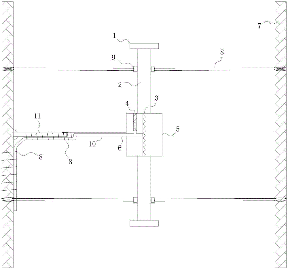
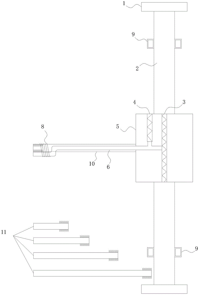
[0031] like figure 1 and 2 , Concrete strain gauge assembly and installation method, including a strain gauge and a fixed steel bar 7, the stress gauge includes a disc 1, a dowel 2, a strain sensor 3 and a temperature sensor 4. By setting the temperature sensor 4, the temperature value in the concrete can be measured. A fixing device is arranged between the stress gauge and the fixed steel bar 7 to fix the stress gauge on the fixed steel bar. Non-direct contact state: the fixing device includes a fixing tube 10 , one end of the fixing tube 10 is connected to a strain gauge, and the wire 6 connected to the strain sensor 3 in the strain gauge extends outward through the pipeline of the fixing tube 10 .

[0032] The stress gauge here includes the shell 5 in the middle, the stress gauge is connected at one end of the fixed pipe 10, and t...


PUM


Abstract

The invention relates to construction and especially relates to a subassembly for fixing a strainmeter in concrete, and an installation method. The invention discloses a subassembly for fixing a strainmeter in concrete and an installation method aiming at solving the problem of inaccurate measurement data of strainmeters in the prior art. The concrete strainmeter subassembly comprises a strainmeter and fixing rebars. The strainmeter comprises wafers, a force transferring rod, and a strain sensor. A fixing device is arranged between the strainmeter and the fixing rebars and is used for fixing the strainmeter on the fixing rebars. The fixing device is arranged on the strainmeter and makes the wafers of the strainmeter and the force transferring rod keep in an indirect contact status; the fixing device comprises a fixing tube, one end of the fixing tube is connected with the strainmeter. A guide line, connecting to the strain sensor, of the strainmeter extends outward through the pipeline of the fixing tube. By installing the fixing device between the fixing rebars and the strainmeter and adjusting the outlet mode of the guide line, the influence of external factors is reduced.

Description

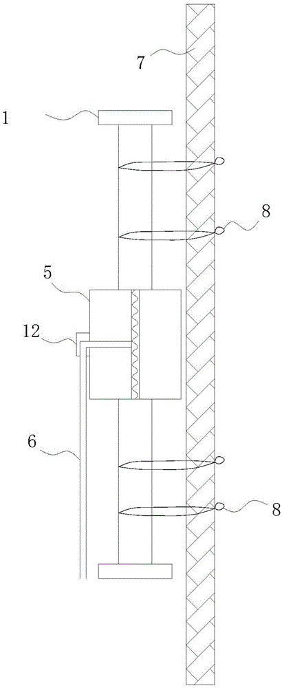
technical field [0001] The invention relates to construction, in particular to a component and an installation method for fixing a strain gauge in concrete. Background technique [0002] At present, the vast majority of concrete strain gauges in engineering are embedded strain gauges, that is, concrete strain gauges are buried in concrete or shotcrete structures, or bound to fixed steel bars to measure the strain of concrete. [0003] like image 3 , the current concrete strain gauge and the installation method of the concrete strain gauge, the strain gauge is bound on the fixed steel bar 7 through the cable tie 8, the disc 1 is in contact with the fixed steel bar, and the wire 6 is drawn out of the shell 5 through the outlet protection device 12. [0004] The way here is in actual engineering, when placing the concrete strain gauge, on the one hand, because the concrete strain gauge has no force point, it is easily disturbed when the concrete is poured or sprayed, and the p...

Claims


Application Information

Patent Timeline
Patent Type & Authority Applications(China)
IPC IPC(8): G01B21/32
CPCG01B21/32
Inventor 王志杰王国栋周平
Owner SOUTHWEST JIAOTONG UNIV
Learn More