Displacement measurement method based on light interference

A displacement measurement and optical interference technology, applied in the field of displacement measurement based on optical interference, can solve the problems of low precision, short range, slow response, etc., and achieve the effect of technical measurement accuracy, stable precision, and precise displacement measurement.

Active Publication Date: 2016-06-15
苏州市鼎苏科技咨询服务有限公司
View PDF5 Cites 4 Cited by
  • Summary
  • Abstract
  • Description
  • Claims
  • Application Information

AI Technical Summary

Problems solved by technology

However, the existing displacement measurement systems generally have a high precision with a short range, and a large range with a low precision. The waveform matching is good, the precision is high, but the operation time is long and the response is slow, and the response is fast, but the precision is low, which cannot meet the needs of modern analysis.

Method used


Image

  • Displacement measurement method based on light interference
  • Displacement measurement method based on light interference
  • Displacement measurement method based on light interference

Examples


Embodiment 1

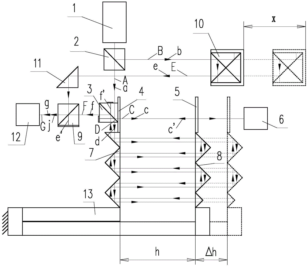
[0067] A displacement measurement method based on optical interference. This method uses the wavelength-selective transmission characteristics of the optical resonant cavity, and obtains the cavity length through the analysis of the transmission wavelength. When the cavity length changes, the transmission wavelength changes accordingly. The receiving device detects and analyzes the transmitted wavelength to obtain the variation of the cavity length, and calculates the displacement of the measured object through the variation of the cavity length.

[0068] The method uses a displacement measurement device based on optical interference for measurement, and includes the following steps:

[0069] ① When the test piece is not moving, the fourth dichroic prism group 10 is in contact with the test piece, and when the system is not turned on, the second reflector 5 and the second right-angle reflective prism group 8 are opposite to the first reflector 4 and the first reflector 4. The ...


PUM


Abstract

The invention provides a displacement measurement method based on light interference and relates to the displacement measurement method. The method is characterized in that, by utilizing a feature that an optical resonant cavity enables wave lengths to be passed selectively, and by analyzing the wave length of transmitted light, cavity length is obtained; when the cavity length changes, the transmission wave length changes therewith; and a photoelectric receiving device detects and analyzes the transmission wave length to obtain cavity length change amount, and displacement of a measured object is calculated through the cavity length change amount. The displacement measurement method can realize precise measurement of the displacement, has the advantages of being high in measurement precision, large in range, capable of crossing from the nm level to the m level, and capable of greatly improving system response time and the like, and is easy to be widely generalized.

Description

technical field [0001] The invention relates to a displacement measurement method, in particular to a displacement measurement method based on light interference. Background technique [0002] In the analysis process of precision machinery design and material development, the acquisition of data such as displacement, vibration amplitude and frequency, deformation, and thermal expansion coefficient of parts and components becomes the key to analysis. However, the existing displacement measurement systems generally have high precision but short range, large range and low precision, good waveform matching, high precision but long operation time and slow response, fast response but low precision, which cannot meet the needs of modern analysis. Contents of the invention [0003] The technical problem to be solved by the present invention is to provide a displacement measurement method based on optical interference, which can realize precise measurement of displacement, has high...

Claims


Application Information

Patent Timeline
Patent Type & Authority Applications(China)
IPC IPC(8): G01B11/02
CPCG01B11/02
Inventor 林澎孙荣敏龙盛保杨灵敏张树林丁伟张宏献许孝忠钟礼君耿雪霄
Owner 苏州市鼎苏科技咨询服务有限公司
Why Eureka
Try Eureka