
Erecting construction process for large-span steel-concrete combination beam

A steel-concrete composite beam and construction technology technology, applied in bridge construction, erection/assembly of bridges, bridges, etc., can solve problems such as inability to meet the requirements of the construction stage of truss steel beams, and the overall weight of the azimuth crane is large.

Active Publication Date: 2016-06-15
CHINA RAILWAY FIRST GRP CO LTD +1
View PDF6 Cites 4 Cited by
  • Summary
  • Abstract
  • Description
  • Claims
  • Application Information

AI Technical Summary

Problems solved by technology

However, the above-mentioned construction method has the following defects and deficiencies in the following three aspects: first, it is greatly affected by terrain conditions, and it is impossible to carry out vertical transportation of steel girders and bridge decks for construction sites with alternating water and land and large height differences; second, for wide bridges Surface structure, the overall weight of the full-slewing crane is relatively large, which cannot meet the requirements of the construction stage of the truss steel beam; Due to the influence of wet joint pouring in the construction of composite composite beams, the anchor points must be displaced later, which cannot meet the needs of the entire construction process.
Therefore, when constructing long-span and wide steel-concrete composite girder cable-stayed bridges, the selection of existing hoisting equipment is limited by the site, and there are problems such as heavy weight and poor use effect

Method used


Image

  • Erecting construction process for large-span steel-concrete combination beam
  • Erecting construction process for large-span steel-concrete combination beam
  • Erecting construction process for large-span steel-concrete combination beam

Examples


Embodiment Construction

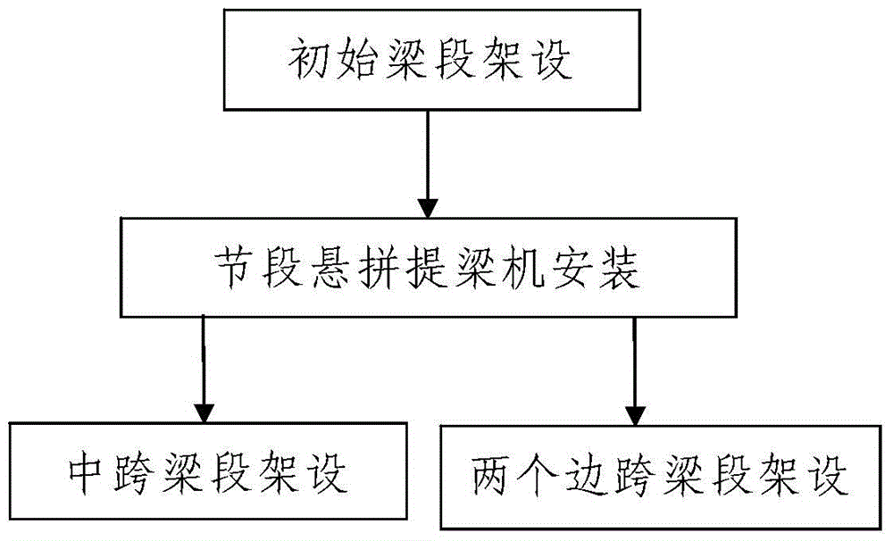
[0139] Such as figure 1 The erection process of a long-span steel-concrete composite girder is shown. The constructed steel-concrete composite girder includes a main girder and a concrete bridge deck paved on the main girder. The main girder is a steel girder and includes a mid-span girder section and two side-span beam sections respectively located on the front and rear sides of the mid-span beam section, the mid-span beam section and the two side-span beams are connected through initial beam sections, and the two initial beam sections The sections are respectively supported on the two piers; the erection of the constructed steel-concrete composite beam includes the following steps:

[0140] Step 1. Erection of initial beam sections: after the construction of the two piers is completed, erect the two initial beam sections respectively;

[0141] Step 2. Erection of the mid-span beam section and the two side-span beam sections: After the erection of the two initial beam sectio...


PUM


Abstract

The invention discloses an erecting construction process for a large-span steel-concrete combination beam. The constructed steel-concrete combination beam comprises a main beam body and a concrete bridge deck slab paved on the main beam body. The main beam body is a steel beam body and comprises a mid-span beam section and two side-span beam sections. The mid-span beam section and the two side-span beam sections are connected through initial beam sections. The erecting construction process for the steel-concrete combination beam comprises the steps that 1, the initial beam sections are erected; and 2, the mid-span beam section and the two side-span beam sections are erected, specifically, the mid-span beam section and the two side-span beam sections are erected through section suspended splicing beam lifters; when erected, the mid-span beam section is erected through the two section suspended splicing beam lifters from the two sides to the middle till the mid-span beam section is closed; when erected, the two side-span beam sections are erected through the two section suspended splicing beam lifters correspondingly. According to the erecting construction process for the large-span steel-concrete combination beam, the steps are simple, the design is reasonable, construction is easy and convenient, and the using effect is good; the erecting process of the steel-concrete combination beam can be easily, conveniently and rapidly competed through the section suspended splicing beam lifters.

Description

technical field [0001] The invention belongs to the technical field of bridge construction, and in particular relates to a construction technique for erecting a large-span steel-concrete composite beam. Background technique [0002] At present, there are many steel girder erection and assembly methods for steel-concrete composite girder cable-stayed bridges in China, mainly including full-slewing crane construction method, mast hanger installation method, integral construction method, full support construction method, jacking construction method, etc. Each method has its own characteristics and scope of application. The construction methods of the existing steel-concrete composite girder cable-stayed bridges are mainly distinguished by the presence or absence of support methods, while the cantilever frame method is more common in the construction of steel-concrete composite girders during on-site construction. For large-span steel-concrete composite beams, the erection meth...

Claims


Application Information

Patent Timeline
IPC IPC(8): E01D21/00
CPCE01D21/00
Inventor 赵金鹏张忠文静国锋田建伟邹松柏赵科鲁鹏博
Owner CHINA RAILWAY FIRST GRP CO LTD
Learn More