
Construction method for cable trough and protective shoulder of high-speed railway roadbed

A technology for high-speed railways and construction methods, which is applied in the installation of cables, ground cables, roads, etc. It can solve the problems of large cutting flying dust, low efficiency, and difficult cutting work, and achieves reduced engineering investment, convenient construction, and small consumables Effect

Active Publication Date: 2016-06-15
CHINA RAILWAY ERYUAN ENG GRP CO LTD
View PDF7 Cites 5 Cited by
  • Summary
  • Abstract
  • Description
  • Claims
  • Application Information

AI Technical Summary

Problems solved by technology

Due to the good filling materials and high compaction of the subgrade surface, the cutting work is very difficult and the efficiency is low, and the cutting surface is often uneven, especially the cut horizontal slope is often uneven, making it easy for water seepage under the cable trough to enter the subgrade Filling body, but also cause a large cutting dust problem

Method used


Image

  • Construction method for cable trough and protective shoulder of high-speed railway roadbed
  • Construction method for cable trough and protective shoulder of high-speed railway roadbed
  • Construction method for cable trough and protective shoulder of high-speed railway roadbed

Examples


Embodiment Construction

[0012] The present invention will be further explained below in conjunction with the drawings and embodiments:

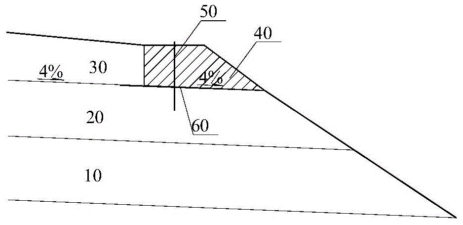
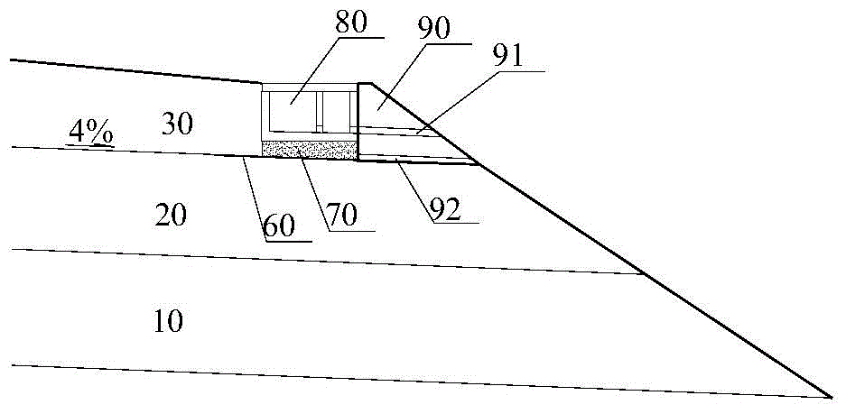
[0013] Reference figure 1 , figure 2 and image 3 , The construction method of a high-speed railway subgrade cable trough and shoulder guard of the present invention, the steps are:

[0014] 1) Fill the road basic body structure 10 and the road base layer structure 20 in layers with a thickness of 0.3m;

[0015] 2) Rolling the top surface of the base layer structure 20 to form a 4% outward lateral drainage slope;

[0016] 3) Lay a composite anti-drainage board 60 on the top surface of the road base structure 20 at the corresponding positions of the cable trough 80 and the shoulder guard 90, and its width extends 0.2m into the inner side of the road base surface structure 30;

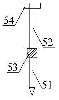
[0017] 4) Place a shoulder mold 40 on the composite waterproof and drainage board 60 at the corresponding positions of the cable groove 80 and the shoulder guard 90. The shoulder mold 40 is provided w...


PUM

PropertyMeasurementUnit
Lengthaaaaaaaaaa

Abstract

The invention provides a construction method for a cable trough and a protective shoulder of a high-speed railway roadbed. By the adoption of the construction method for the cable trough and the protective shoulder of the high-speed railway roadbed, the problem caused by cutting of a roadbed surface structure can be effectively solved; and the construction method has the characteristics of being easy to operate, capable of saving time, economical and the like. The construction method comprises the steps that a roadbed body structure and a roadbed bottom layer structure which are located under the roadbed surface structure are filled in a layered mode; the top surface of a roadbed bottom layer structure is rolled to be flat; a composite waterproof and drainage plate is laid in the positions, corresponding to the cable trough and the protective shoulder, of the top surface of the roadbed bottom layer structure; a road shoulder mold is arranged in the positions, corresponding to the cable trough and the protective shoulder, of the composite waterproof and drainage plate, and a reserved hole is formed in the road shoulder mold; a fixing screw is inserted into the reserved hole of the road shoulder mold; the road shoulder mold is fixed to the top of the roadbed bottom layer structure by means of a movable rod on the upper portion of the fixing screw through a nut; the portion, on the inner side of the road shoulder mold, of the roadbed surface structure is filled in a layered mode; the nut on the movable rod is taken down; the road shoulder mold is dismounted; a connecting buckle in the fixing screw is opened, and the movable rod in the fixing screw is taken out; a gravel pervious bed at the bottom of the cable trough is laid; the cable trough is placed; and the concrete protective shoulder is cast in place in a layered mode.

Description

Technical field [0001] The invention relates to railway engineering, in particular to a construction method in which a high-speed railway cable trough is arranged on a subgrade shoulder. Background technique [0002] High-speed railway cable troughs need to be set on the shoulder of the subgrade. The current common practice is to remove the subgrade surface filling at the filled shoulder position by cutting after the subgrade construction is completed, and then construct the cable trench on the cut surface And roadbed shoulder pads. Due to the good filling materials and high compaction of the roadbed surface, the cutting work is very difficult and inefficient, and the cutting surface is often uneven, especially the cut horizontal slope is often uneven, making it easy for water seepage under the cable trough to enter the roadbed The filling body will also cause a larger cutting fly dust problem. For this reason, there is an urgent need for a construction method of high-speed rai...

Claims


Application Information

Patent Timeline
IPC IPC(8): E01B2/00H02G9/02
CPCE01B2/006E01B2204/07H02G9/02
Inventor 姚裕春李安洪刘洋魏永幸袁碧玉
Owner CHINA RAILWAY ERYUAN ENG GRP CO LTD
Learn More