
End surface groove machining forming equipment for bearing inner rings

A technology for bearing inner rings and forming equipment, applied in metal processing equipment, grinding/polishing equipment, manufacturing tools, etc., can solve problems such as high processing costs, low production efficiency, and inability to scale mass production

Active Publication Date: 2016-06-15
HANDAN HONGLI BEARING
View PDF4 Cites 2 Cited by
  • Summary
  • Abstract
  • Description
  • Claims
  • Application Information

AI Technical Summary

Problems solved by technology

[0002] For the bearing inner ring used on machinery and equipment, it is necessary to process four or more symmetrical U-shaped grooves or rectangular grooves on the end face of the bearing inner ring. The current processing method is milling machine slot milling, one clamping at a time, and the production efficiency is high. Low, high processing cost, not capable of large-scale mass production

Method used


Image

  • End surface groove machining forming equipment for bearing inner rings
  • End surface groove machining forming equipment for bearing inner rings
  • End surface groove machining forming equipment for bearing inner rings

Examples


Embodiment Construction

[0024] In order to make the object, technical solution and advantages of the present invention clearer, the present invention will be further described in detail below in conjunction with the accompanying drawings and embodiments. It should be understood that the specific embodiments described here are only used to explain the present invention, not to limit the present invention.

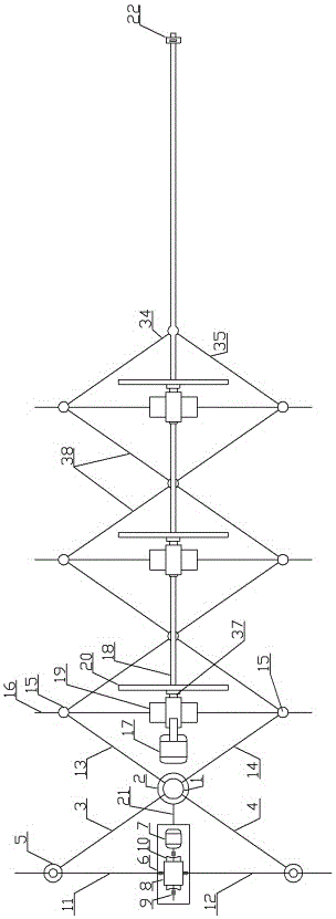
[0025] Please refer to Figure 1-5 , a bearing inner ring end surface groove processing and forming equipment of the present invention, including: a base 33, a column 1, a support frame 22, a grinding wheel distance adjustment mechanism, a power mechanism, a bearing inner ring feeding mechanism, and a cam intermittent mechanism. The column 1 and the support frame 22 are fixedly installed on the base 33 , the column 1 is provided with steps, and the base 33 is provided with a guide rail slider 40 .

[0026] The grinding wheel distance adjustment mechanism includes: hinged bushing 2, left hinged swi...


PUM


Abstract

The invention relates to bearing machining equipment, in particular to end surface groove machining forming equipment for bearing inner rings. The machining forming equipment comprises a base, a stand column, a supporting frame, an abrasive wheel distance adjustment mechanism, a power mechanism and a bearing inner ring feeding mechanism. The bearing inner rings are arranged in rhombus structures. A screw adjusting rolling wheel is rotated. A clockwise screw nut and an anticlockwise screw nut move outwards. The rhombus structures contract to clamp and fix the bearing inner rings. A servo motor is started and sequentially drives a worm, a worm wheel, a left-handed screw and a right-handed screw to rotate. The extension angles of first swinging arms and second swinging arms are adjusted. The distance between every two adjacent abrasive wheels is changed. A power motor is started, and the abrasive wheels rotate at high speed to carry out end surface groove machining on the bearing inner rings. The multiple bearing inner rings can be clamped in the machining forming equipment at a time, the production efficiency is high, the machining cost is low, and large-scale volume production can be realized.

Description

technical field [0001] The invention relates to a bearing processing equipment, in particular to a bearing inner ring end surface groove processing and forming equipment. Background technique [0002] For the bearing inner ring used on machinery and equipment, it is necessary to process four or more symmetrical U-shaped grooves or rectangular grooves on the end face of the bearing inner ring. The current processing method is milling machine slot milling, one clamping at a time, and the production efficiency is high. Low, high processing costs, can not be mass-produced on a large scale. Contents of the invention [0003] In order to overcome the above defects, the object of the present invention is to provide a bearing inner ring end surface groove processing and forming equipment with high production efficiency and capable of large-scale batch processing. [0004] The purpose of the present invention is achieved through the following technical solutions: [0005] A beari...

Claims


Application Information

Patent Timeline
IPC IPC(8): B24B19/02B24B27/00B24B41/00B24B47/12B24B47/00
CPCB24B19/02B24B27/0076B24B41/005B24B47/00B24B47/12
Inventor 赵丰王黎峰王晓博
Owner HANDAN HONGLI BEARING
Learn More