
Method of etching cd pattern on the surface of substrate and laser cutting to form logo

A technology of substrate surface and laser cutting, applied in laser welding equipment, metal processing equipment, photoengraving process of pattern surface, etc., can solve the problems of affecting LOGO aesthetics, low processing accuracy, and high cost of CD pattern molds. To achieve the effect of lasting colorful effect, strong three-dimensional effect and good glare effect

Active Publication Date: 2017-08-25
江苏京晶光电科技有限公司
View PDF1 Cites 0 Cited by
  • Summary
  • Abstract
  • Description
  • Claims
  • Application Information

AI Technical Summary

Problems solved by technology

However, the ink used in this patent is printed on the surface of hard materials, the adhesion is not high enough, it is easy to fall off, it cannot prevent scratches, the processing accuracy is not high, and it is impossible to make nano-level CD patterns. In addition, due to the high power density of laser cutting The laser beam irradiates the material to be cut, so that the material is quickly heated to the melting temperature, the silk screen layer cannot withstand such a high temperature, and the edge ablation layer is large during laser cutting, which will affect the aesthetics of the LOGO
[0007] For the third processing method, the cost of CD pattern mold is high, the mold life is short, and the molding efficiency is low, which is only suitable for the base material of plastic material

Method used


Image

  • Method of etching cd pattern on the surface of substrate and laser cutting to form logo
  • Method of etching cd pattern on the surface of substrate and laser cutting to form logo
  • Method of etching cd pattern on the surface of substrate and laser cutting to form logo

Examples


Embodiment Construction

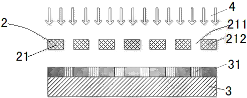
[0049] see Figure 1~Figure 15 According to the present invention, a method for etching and processing CD lines on the surface of a substrate and laser cutting to form a LOGO includes the following steps:

[0050] 1) Make a mask

[0051] According to the different specifications of the CD pattern 1 to be processed, the mask plate 2 is designed and manufactured according to the ratio of the area of ​​the CD pattern 1: the area of ​​the mask plate 2 = 1:1 or 4:1 or 5:1, and is formed in the middle of the surface of the mask plate 2 A CD pattern area 21 corresponding to the CD pattern 1, the CD pattern area 21 includes a light-transmitting area 211 and an opaque area 212;

[0052] Among them, there are currently three types of photolithography machines on the market, which are proximity or contact photolithography machines. The CD pattern area: mask area = 1:1, and this type will be selected when the line width and line space width are above 1 μm. Lithography machine; CD patter...


PUM

PropertyMeasurementUnit
thicknessaaaaaaaaaa
thicknessaaaaaaaaaa

Abstract

The invention provides a method for conducting CD pattern corrosion machining and laser cutting on the surface of a base material to form a LOGO. The method comprises the first step of mask plate manufacturing, the second step of light resistance film coating and baking, the third step of exposure and baking, the fourth step of developing and baking, the fourth step of etching and the sixth step of laser cutting. The method is high in efficiency and precision and wide in application range. Due to the fact that the surface of the base material is polished, and CD patterns are provided with many convex blocks microcosmically, irradiation of light to the surface of the base material is equivalent to the fact that chromatic dispersion of many small prisms can occur, and different colors are presented. Due to the fact that the CD patterns are etched on the base material, the risk of falling cannot happen, and the colorful effect is more lasting.

Description

technical field [0001] The invention belongs to the technical field of surface treatment, and in particular relates to a method for etching CD lines on the surface of a substrate and laser cutting to form a LOGO. Background technique [0002] With the development of society, people's requirements for beauty are getting higher and higher. The LOGO that will be used in many fields is no longer a single color. The surface of the polished substrate is etched to produce CD patterns like many small ones. Prism, when visible light is irradiated on the surface, it will disperse and present a colorful and dazzling effect. With the advancement of science and technology, the current optical fiber cutting machine has the characteristics of small focusing spot, fine cutting line, high processing precision and low energy consumption. It can realize High-precision LOGO cutting, and the edge damage area is small, which will not affect the appearance of LOGO. [0003] The existing CD patter...

Claims


Application Information

Patent Timeline
Patent Type & Authority Patents(China)
IPC IPC(8): B23K26/066B23K26/38B23K26/12G03F7/00
CPCB23K26/066B23K26/123B23K26/38G03F7/0035
Inventor 李建勳郑松森
Owner 江苏京晶光电科技有限公司
Learn More