Portable backpack descent control device
A descender and knapsack-type technology, which is applied in the field of convenient backpack descender, can solve the problems that people’s life safety cannot be guaranteed, hidden dangers in personal safety, and huge descender, and achieve simple structure and convenient control , suitable for a wide range of effects
- Summary
- Abstract
- Description
- Claims
- Application Information
AI Technical Summary
Problems solved by technology
Method used
Image
Examples
Embodiment 1
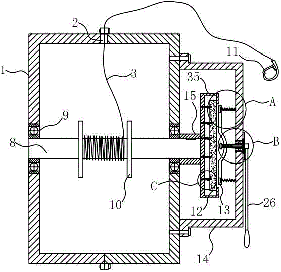
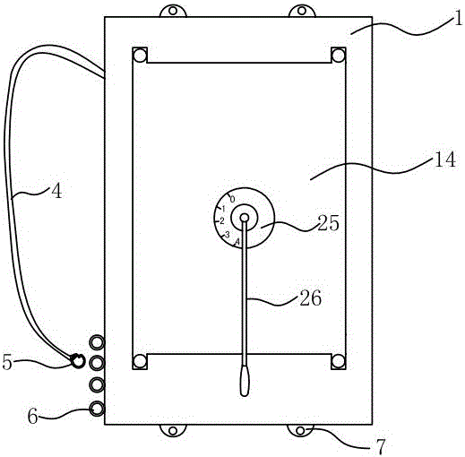
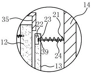
[0029] Such as figure 1 , 2, 3, 4, 5, 6, and 7, a convenient knapsack-type descending device includes a housing 1 provided with a descending rope outlet 2, a friction plate and a descending rope 3, and the housing 1 is provided with a There is a double-shoulder strap 4. When escaping, the slow descender is carried on the body. One end of the double-shoulder strap 4 is fixed on the housing 1 by riveting. The other end of the double-shoulder strap 4 is provided with a buckle 5. The housing 1 There is a pull ring 6 for hooking the shoulder strap 4 matched with the buckle 5, and the pull ring 6 is arranged vertically. In order to adapt to the crowd of different body types, the said pull ring 6 is set in multiples, and different choices are made according to different body types. The pull ring 6 in the position further describes the housing 1, the housing includes left and right housings, the left and right housings are respectively provided with a plurality of connecting parts 7 ...
Embodiment 2
[0031] Such as Figure 8 , 9 , shown in 10 and 11, differs from Embodiment 1 in that: it also includes a control system, the control system includes a speed sensor 27 arranged on the rotating shaft 8, a signal receiver receiving the speed signal of the speed sensor 27, and processing speed The signal CPU sends the signal processed by the CPU to the signal transmitter of the control device, and the speed sensor 27, the signal receiver, and the signal transmitter are all electrically connected to the CPU. The control device includes a spline groove 28 arranged on the friction box 14 and a spline shaft 29 cooperating with the spline groove 28. One end of the spline shaft 29 is fixed to the secondary friction plate 13, which is well known to those skilled in the art. Fixing can be by welding or screw connection. The other end of the spline shaft 29 is fixed with a stopper 30 that prevents the spline shaft 29 from breaking away from the spline groove 28, and also includes a hydrau...
Embodiment 3
[0033] Such as Figure 12 As shown, the difference from Embodiments 1 and 2 is that the control device includes an adjustment rod 38 fixedly connected with the secondary friction plate 13, and the adjustment rod 38 is provided with threads and is threadedly connected with the friction box 14, and is connected with the adjustment rod 38. A handle is attached to the rod 38 .
PUM
 Abstract
Description
Claims
Application Information
 - R&D
- Intellectual Property
- Life Sciences
- Materials
- Tech Scout
- Unparalleled Data Quality
- Higher Quality Content
- 60% Fewer Hallucinations
Browse by: Latest US Patents, China's latest patents, Technical Efficacy Thesaurus, Application Domain, Technology Topic, Popular Technical Reports.
© 2025 PatSnap. All rights reserved.Legal|Privacy policy|Modern Slavery Act Transparency Statement|Sitemap|About US| Contact US: help@patsnap.com


