A heat pump tail heat utilization countercurrent dryer

A dryer and heat pump type technology, which is applied in the field of heat pump type tail heat utilization countercurrent dryer, can solve problems such as difficulty in disassembly, and achieve the effects of preventing fatigue fracture, achieving remarkable effect and enhancing bearing capacity.

Active Publication Date: 2018-07-17
NANTONG PRATT MACHINERY
View PDF7 Cites 0 Cited by
  • Summary
  • Abstract
  • Description
  • Claims
  • Application Information

AI Technical Summary

Problems solved by technology

In the actual assembly of shafts and holes with transmission threads, in order to achieve large load-bearing functions, the size of the threaded shafts and matching nut-like components are relatively large, and it is often easy and convenient to screw in during assembly, and It can realize the automatic and continuous locking of the bearing capacity during use, so it is very reliable, but when it is disassembled, the assembly is often very tight, and disassembly is very difficult. It is particularly important to realize simple and easy disassembly under this condition

Method used


Image

  • A heat pump tail heat utilization countercurrent dryer
  • A heat pump tail heat utilization countercurrent dryer
  • A heat pump tail heat utilization countercurrent dryer

Examples


Embodiment Construction

[0032] Now in conjunction with accompanying drawing, the present invention is described in further detail.

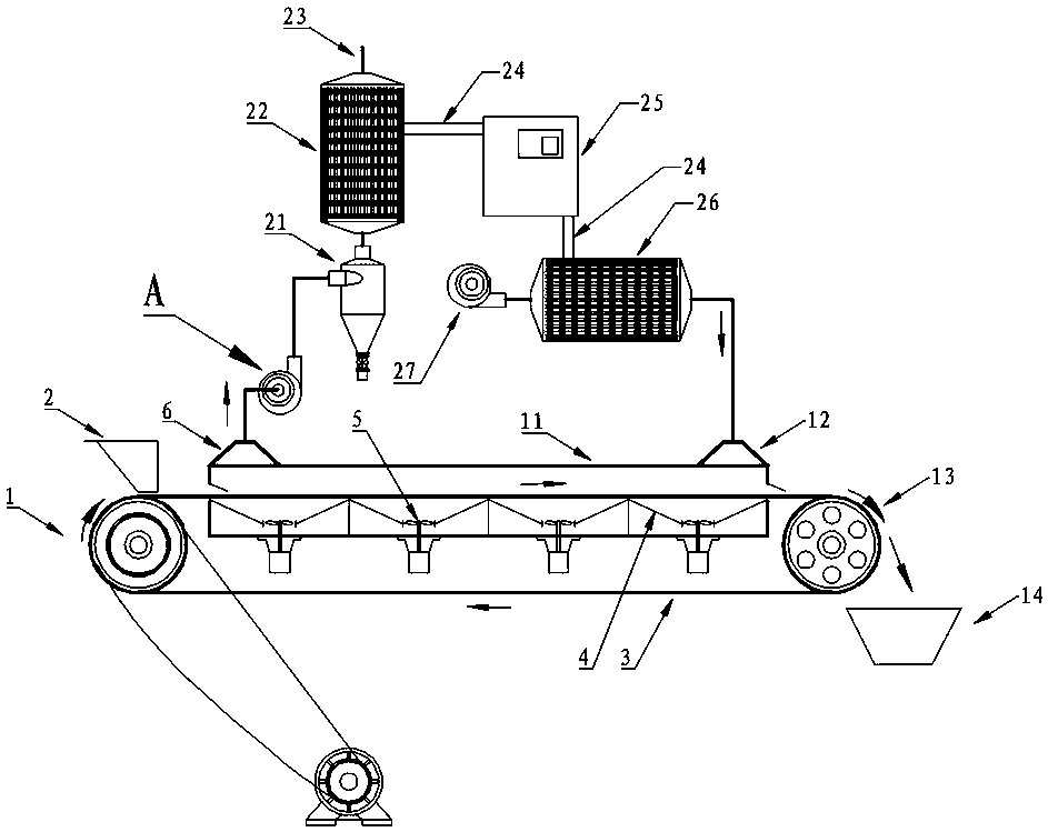
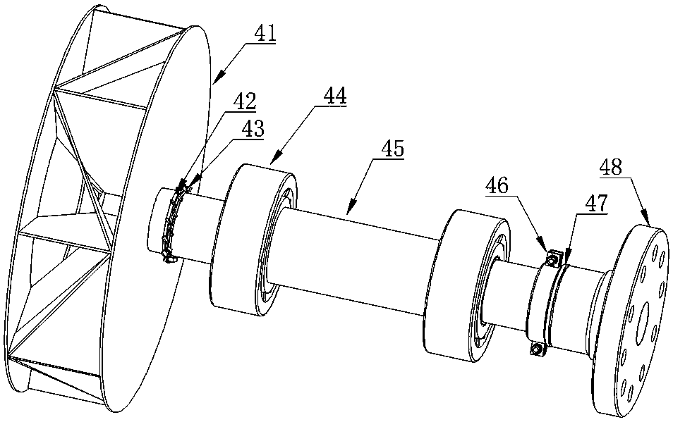
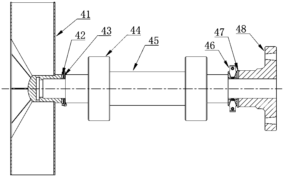
[0033] Such as figure 1 , figure 2 , image 3 , Figure 4 , Figure 5 , Figure 6 , Figure 7 , Figure 8 and Figure 9 The shown heat pump tail heat utilization countercurrent dryer includes a dryer 11 and an induced draft fan A. The two ends of the dryer 11 are respectively provided with an exhaust hood 6 and an air intake hood 12. The exhaust hood 6 is connected to the induced draft fan A, and the induced draft fan A is emptied after being connected to the evaporator 22 of the heat pump system through the cyclone dust collector 21; the evaporator 22 of the heat pump system is connected to the main engine 25 through the refrigerant pipe 24, and the main engine 25 is connected to the condenser 26 through the refrigerant pipe 24; the air outlet end of the blower 27 is passed through the condenser 26 is connected to the air inlet cover 12; the induced draft fan ...


PUM


Abstract

The invention discloses a heat-pump reversed-current drying machine for tail heat utilization. According to the invention, an air draft hood of the drying machine is connected with an induced draft fan, and the induced draft fan is connected with an evaporator of a heat pump system via a cyclone dust remover, and then is emptied; the evaporator of the heat pump system is connected with a host via a refrigerant tube, and the host is connected with a condenser via the refrigerant tube; an exhaust end of an air blower is connected with an air intake hood via the condenser; and blades of an induced draft fan impeller are arranged to be in a radial shape with impeller-shaft radial and central symmetry, and ash can be timely cleaned by virtue of a centrifugal force, thus security incidents are avoided. According to the invention, drying efficiency is improved, and energy conservation and emission reduction are realized; and more importantly, a detachment technology for the induced draft fan is greatly improved, and a pressure of components such as a nut on the end surface of a shaft shoulder of a screw during detachment for the induced draft fan can be simply eliminated, thus the problem is effectively solved that the induced draft fan is not easy to detach due to continuously automatic locking in thread assembly for the induced draft fan under the action of a load. The heat-pump reversed-current drying machine for tail heat utilization is especially suitable for convenient detachment for a large fan after thread locking, and has a particularly remarkable effect.

Description

technical field [0001] The invention relates to a dryer, in particular to a heat pump tail heat utilization countercurrent dryer which does not accumulate dust in a fan and is easy to disassemble and repair. Background technique [0002] People generally refer to drying with a drying temperature below 60 degrees Celsius as low-temperature drying. Low-temperature drying is widely used in the drying of heat-sensitive materials such as crop seeds, Chinese medicinal materials, and biological products. Due to its mature technology, strong adaptability, low operating cost and high reliability, hot air dryer is still one of the first choice equipment for low temperature drying. Low-temperature drying is less likely to utilize tail heat due to the lower temperature of exhaust gas. If the penetration and countercurrent drying of materials can be realized in the hot-air low-temperature drying process, and the tail heat can be effectively recovered, it will be of great significance fo...

Claims


Application Information

Patent Timeline
Patent Type & Authority Patents(China)
IPC IPC(8): F26B17/04F26B21/00F26B25/00F04D29/64
CPCF04D29/646F26B17/04F26B21/00F26B25/00
Inventor 张旭银永忠张思言
Owner NANTONG PRATT MACHINERY
Why Eureka
Try Eureka