
LNG air temperature type gasification device utilizing photovoltaic power generation and method of LNG air temperature type gasification device

An air-temperature gasifier and photovoltaic power generation technology, which is applied in the field of LNG gasification, can solve problems such as accumulation of frost and icing, and achieve the effects of increasing the laying area, reducing costs, and improving safety and reliability.

Active Publication Date: 2016-06-08
NORTH CHINA ELECTRIC POWER UNIV (BAODING)
View PDF10 Cites 3 Cited by
  • Summary
  • Abstract
  • Description
  • Claims
  • Application Information

AI Technical Summary

Problems solved by technology

[0004] The invention aims to solve the problem of frosting and freezing on the outer surface of the LNG air-temperature gasifier during use, ensure the gasification capacity of the LNG air-temperature gasifier, and reduce the configuration cost of the LNG air-temperature gasifier; Based on this, the present invention provides an LNG air-temperature gasification device and method thereof utilizing photovoltaic power generation

Method used


Image

  • LNG air temperature type gasification device utilizing photovoltaic power generation and method of LNG air temperature type gasification device
  • LNG air temperature type gasification device utilizing photovoltaic power generation and method of LNG air temperature type gasification device
  • LNG air temperature type gasification device utilizing photovoltaic power generation and method of LNG air temperature type gasification device

Examples


Embodiment Construction

[0023] The present invention will be further described below in conjunction with the drawings and specific embodiments. It should be emphasized that the following description is only exemplary, and is not intended to limit the scope of the present invention and its application.

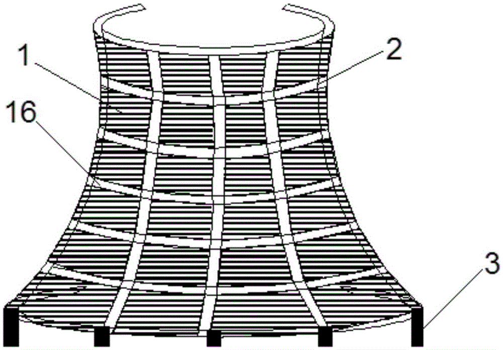
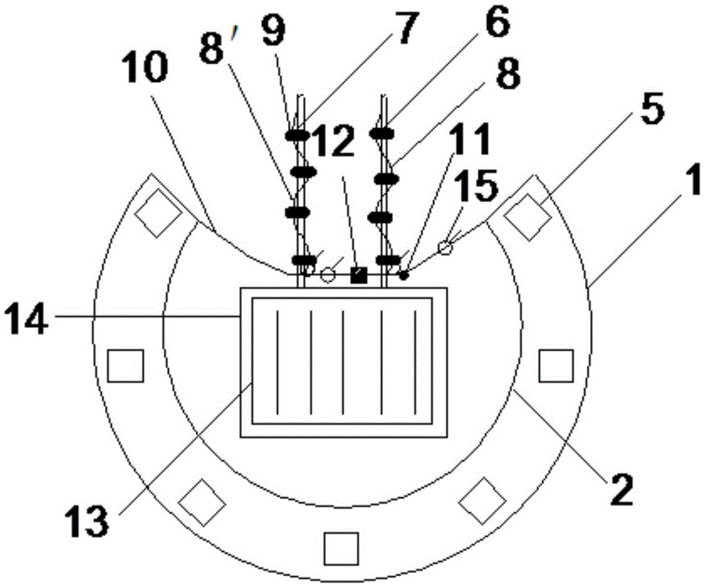
[0024] Such as figure 1 Shown is an LNG air-temperature gasification device using photovoltaic power generation, which includes a photovoltaic power generation device, an LNG air-temperature vaporizer 13, an electric wire 10, a first MI heating cable 8, a second MI heating cable 8'and Switch 15;

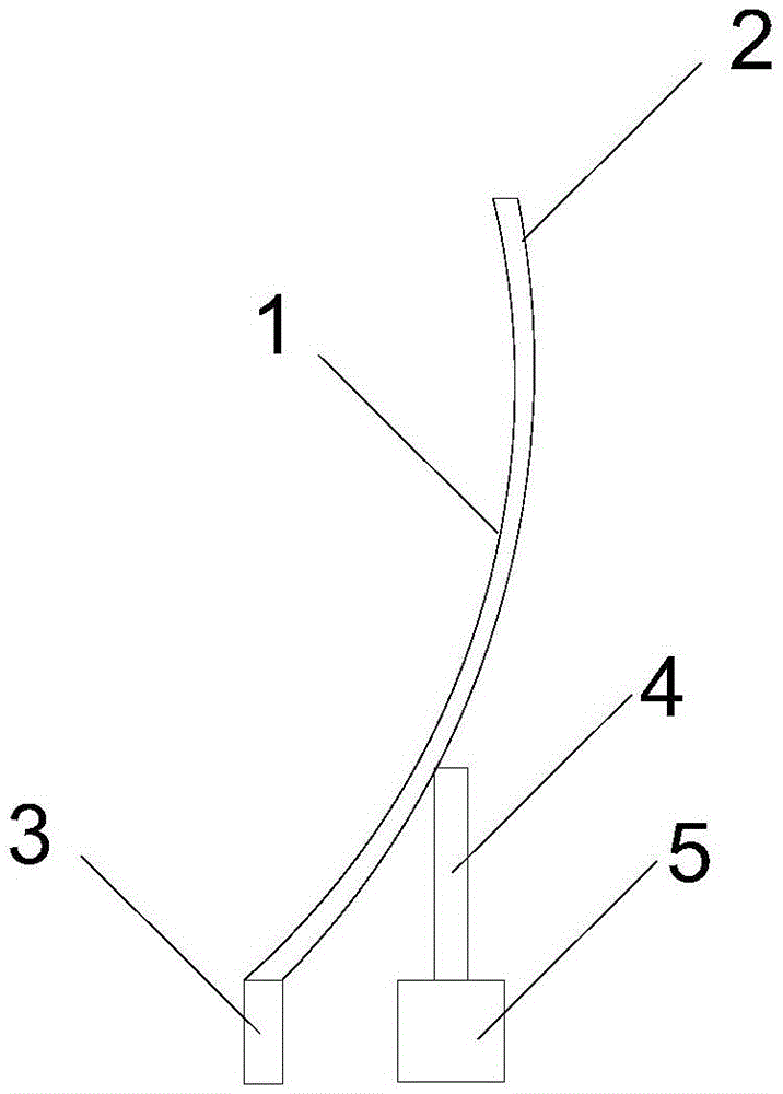
[0025] The photovoltaic power generation device includes a thin film solar panel 1, a lining board 2 and a bottom bracket 3; the lining board 2 is hyperbolic, opening to the north, the bottom projection is 3 / 4 circle, the top is not capped, and the lining board 2 has an upper edge Strip slits 16 are opened at equal intervals in the latitude and longitude directions to form a strip-shaped tuyere; a wire 10 is con...


PUM


Abstract

The invention relates to an LNG air temperature type gasification device utilizing photovoltaic power generation and a method of the LNG air temperature type gasification device. A substrate of a photovoltaic power generation device is in a dual curve shape, the top of the substrate is not sealed, an opening is formed in the substrate northwards, an electric wire is connected between the sides of the opening, and a thin film solar cell panel is laid on the outer surface of the substrate. An LNG air temperature type gasifier is supported in the photovoltaic power generation device. MI heating cables are wound around a gasifier inlet pipeline and a gasifier outlet pipeline, and connected with the electric wire. Electric energy generated by the photovoltaic power generation device is converted into heat energy through the MI heating cable on the gasifier inlet pipeline to heat inlet LNG. When the temperature of outlet natural gas is lower than 5 DEG C, the outlet natural gas is heated through the MI heating cable on the gasifier outlet pipeline, so that energy consumption generated by subsequently utilizing a water bath type gasifier for reheating is eliminated or reduced. According to the LNG air temperature type gasification device, solar energy is fully utilized, the gasification capacity of the LNG air temperature type gasifier is guaranteed, and the phenomenon that the outer surface of the LNG air temperature type gasifier is frosted and frozen is relieved or eliminated.

Description

Technical field [0001] The invention belongs to the technical field of LNG gasification using photovoltaic power generation, and particularly relates to an LNG air-temperature gasification device and method using photovoltaic power generation. Background technique [0002] Liquefied natural gas (LNG for short) is an important source of urban gas in my country, and it needs to be gasified from liquid to gas before being supplied to users for application. Since the temperature of LNG is -162°C, LNG air-heated vaporizers are often used to absorb the heat of the surrounding air to vaporize LNG. However, the gasification capacity of the air-heated gasifier is greatly affected by the ambient temperature. When the temperature is low (especially in severe cold areas), the gasification capacity may not meet the requirements, and the water vapor in the air will be vaporized. The outer surface of the device is condensed and solidified, causing frost and ice. For this reason, two sets of a...

Claims


Application Information

Patent Timeline
Patent Type & Authority Applications(China)
IPC IPC(8): F17C7/04H02S20/10
CPCF17C7/04F17C2221/033F17C2223/0161F17C2225/0123F17C2227/033F17C2227/0374H02S20/00Y02E10/50
Inventor 时国华李丹刘新雨田胜楠
Owner NORTH CHINA ELECTRIC POWER UNIV (BAODING)
Learn More