Crankshaft type compressor

A technology for compressors and crankshafts, applied in the field of compressors, which can solve problems such as easy breakage of the suction valve, short service life, and poor stress on the valve, so as to protect it from being broken by impact, relieve the rapid increase of air flow, The effect of structural simplification

Inactive Publication Date: 2016-06-08
FENGHUA ZHEXING XINHUI REFRIGERATION EQUIP CO LTD
View PDF6 Cites 0 Cited by
  • Summary
  • Abstract
  • Description
  • Claims
  • Application Information

AI Technical Summary

Problems solved by technology

[0003] The shape of the suction valve plate of the valve plate is generally a long tongue shape, which will be bent repeatedly during the working process. The stopper is a single-point (or single-line) impact, so the force of this valve is poor and the service life is short. Once the compressor has a liquid hammer, the suction valve is more likely to break

Method used


Image

  • Crankshaft type compressor
  • Crankshaft type compressor
  • Crankshaft type compressor

Examples


Embodiment Construction

[0018] The present invention will be further described in detail below in conjunction with the accompanying drawings and embodiments.

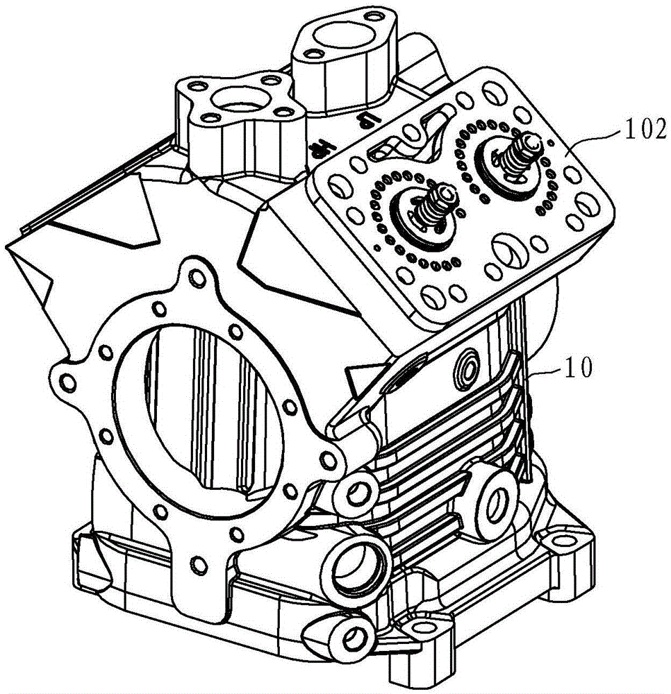
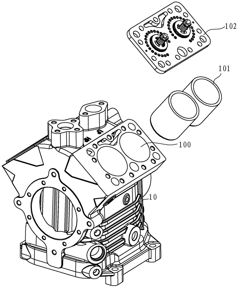
[0019] Such as figure 1 and figure 2 As shown, the crankshaft compressor in this embodiment includes a cylinder body 10 with a cylinder hole 100 and a valve plate assembly 102 disposed on the end surface of the cylinder hole 100 , and a cylinder liner 101 is embedded in the cylinder hole 100 .

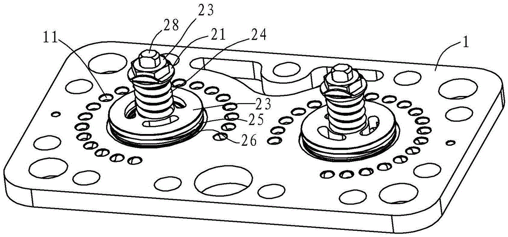
[0020] Such as image 3 , Figure 4 and Figure 5 As shown, the valve plate assembly in this embodiment includes a valve plate 1, an exhaust valve plate 3 and an air intake valve plate 4. The valve plate 1 has an exhaust hole 12 and an air intake hole 11, and the exhaust valve plate 3 is provided with The first surface of the valve plate 1 can open and close the exhaust hole 12, the suction valve plate 4 is arranged on the second surface of the valve plate 1 and can open and close the suction hole 11, the middle part of the valve plate 1 has a mo...


PUM


Abstract

A crankshaft type compressor comprises a cylinder body with a cylinder hole and a valve board assembly arranged on the end face of the cylinder hole. The valve board assembly comprises a valve board, discharge valve plates and air suction valve plates. Exhaust holes and air suction holes are formed in the valve board. The exhaust holes are annularly formed in the valve board and surround a mounting hole. Correspondingly, the discharge valve plates are provided with annular sealing faces. The air suction holes are annularly formed in the valve board and surround the exhaust holes. Correspondingly, the air suction valve plates are provided with annular sealing parts. Compression springs, stoppers and corrugated elastic sheets are sequentially arranged on the back faces of the discharge valve plates from outside to inside. Compared with the prior art, the crankshaft type compressor has the beneficial effects that the situation that air flow is rapidly increased is relieved, and the discharge valve plates are protected against impact fractures.

Description

technical field [0001] The present invention relates to a compressor. Background technique [0002] At present, common crankshaft compressors include a cylinder block and a valve plate. The cylinder bore of the cylinder block is provided with a valve plate assembly. The widely used valve plate structure is mainly a reed valve plate structure, such as Figure 6 As shown, the valve plate structure includes valve plate 1a, exhaust valve plate 5a, exhaust spring plate 4a, limiter 3a, spacer 7a, suction valve plate 6a and suction spring plate 8a, and valve plate 1a is provided with The exhaust hole 11a and the suction hole 12a, the screw 2a sequentially connect the spacer 7a, the stopper 3a, the exhaust spring piece 4a and one end of the exhaust valve piece 5a to the first surface of the valve plate 1a and use the nut 21a Fixed, the other end of the exhaust valve plate 5a is facing the exhaust hole 11a, one end of the suction valve plate 6a is fixed on the second surface of the v...

Claims


Application Information

Patent Timeline
IPC IPC(8): F04B39/10F04B39/12
CPCF04B39/1046F04B39/102F04B39/1033F04B39/122F04B39/126
Inventor 林伦华刘铭刚
Owner FENGHUA ZHEXING XINHUI REFRIGERATION EQUIP CO LTD
Why Eureka
Try Eureka