
Wind power generator

A technology for wind power generators and driving motors, which is applied in the direction of wind power generators, wind power motor combinations, and wind power generation. It can solve the problems of large influence of hydraulic oil temperature, unstable wind conditions, and high cost. Safe to use

Active Publication Date: 2016-06-08
DATANG ERYUAN FENGYU WIND POWER
View PDF3 Cites 6 Cited by
  • Summary
  • Abstract
  • Description
  • Claims
  • Application Information

AI Technical Summary

Problems solved by technology

In addition, the wind conditions are unstable. Sometimes there is no wind and sometimes there are destructive winds. These are practical problems that must be solved in wind power generation.
[0004] At present, the automatic pitch control system of wind turbines can be roughly divided into three types, namely hydraulic pitch system, electric pitch system and centrifugal passive pitch system. The hydraulic pitch system is prone to oil leakage, the controller is expensive, and the hydraulic oil It is greatly affected by temperature, needs regular oil changes and filters, and many other defects. It is rarely used in the market at present. Compared with the hydraulic pitch system, the electric pitch system has certain advantages and currently occupies the main market, but because of its high cost , is too complicated, has extremely strict requirements on components, and is afraid of lightning and needs frequent maintenance, etc., so it is not a perfect solution. The reason why it occupies the main market is also a helpless move of the wind power industry. Due to the structure, it can only be used in small and medium-sized wind turbines, and the performance is not ideal

Method used


Image

  • Wind power generator
  • Wind power generator
  • Wind power generator

Examples


Embodiment Construction

[0051] The present invention will be further described in detail below in conjunction with the accompanying drawings, so that those skilled in the art can implement it with reference to the description.

[0052] It should be understood that terms such as "having", "comprising" and "including" as used herein do not entail the presence or addition of one or more other elements or combinations thereof.

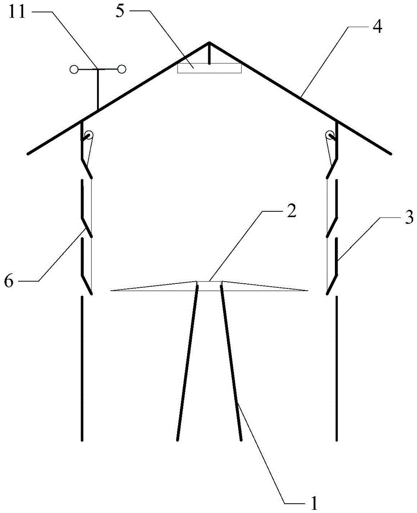
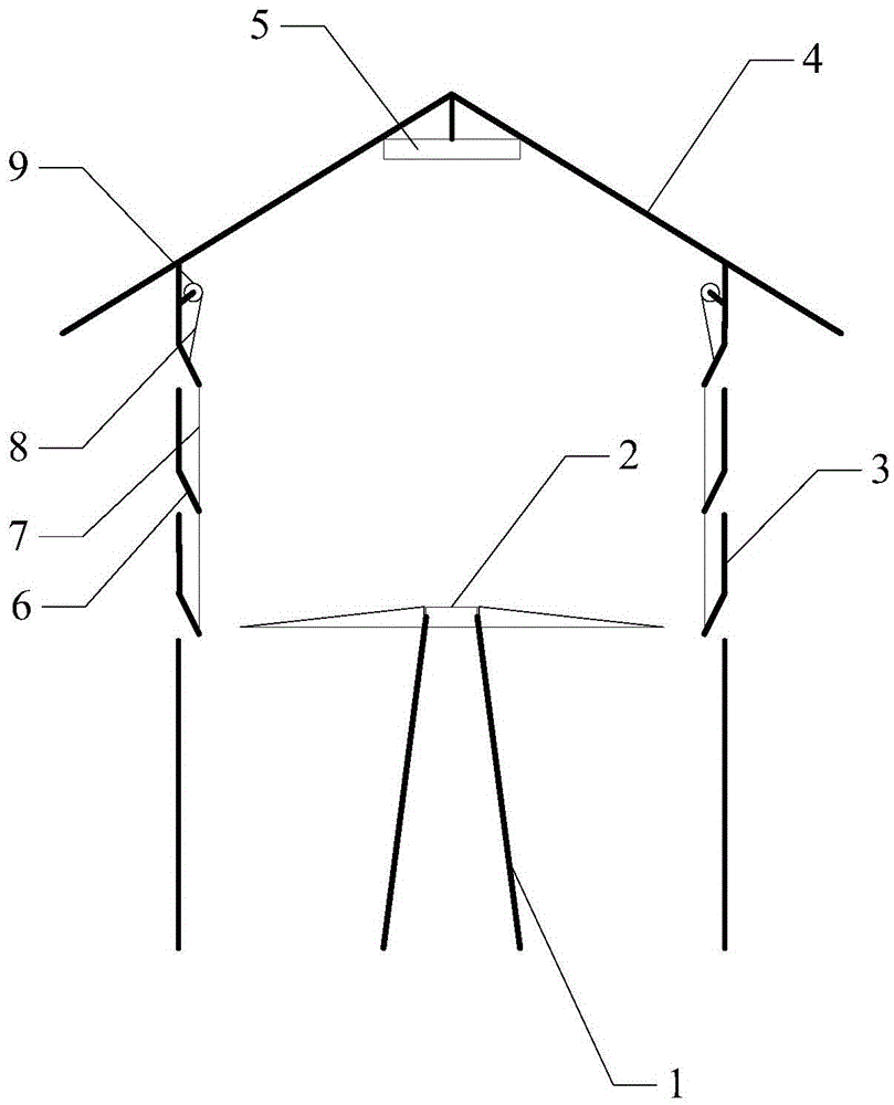
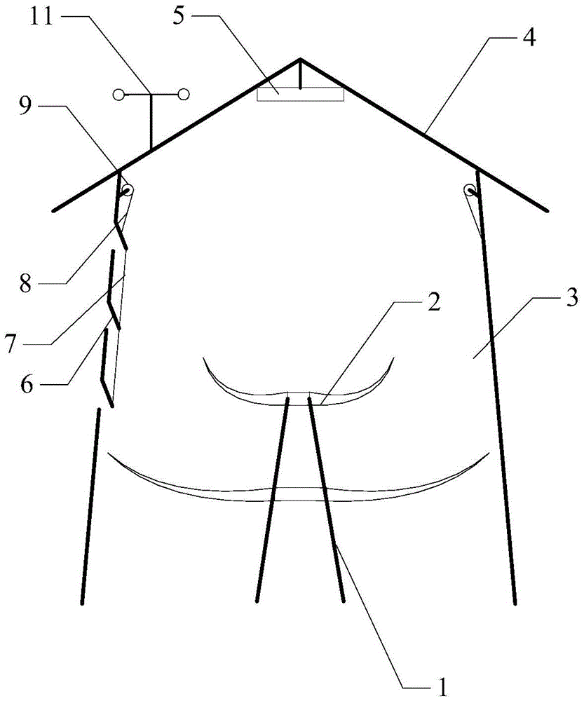
[0053] Such as figure 1 and Figure 4 As shown, the present invention provides a kind of wind generator, comprising:

[0054] Tower 1;

[0055] At least one impeller part 2, which is arranged on the upper end of the tower, the at least one impeller part includes the main shaft of the wind blade, the main shaft of the wind blade is coaxial with the tower; and the blade is arranged around the main shaft of the wind blade , to drive the main shaft of the fan blade to rotate;

[0056] Wind deflector 3, which is a hollow cylinder, the tower is vertically arranged in the cavity of ...


PUM


Abstract

The invention discloses a wind power generator. The wind power generator comprises a tower, at least one impeller part, a wind guide hood, a plurality of wind guide windows, a cap body, a first drive device, a second drive device, a wind power and wind direction measurer and a control device, wherein the at least one impeller part is arranged at the upper end of the tower, and comprises a wind blade main shaft and blades; the wind guide hood is a hollow cylinder, and the tower is vertically arranged in a cavity of the hollow cylinder; the plurality of wind guide windows are uniformly arranged on the sidewall of the wind guide hood in columns; the cap body is arranged at an opening in the upper end of the wind guide hood in a covering manner; the first drive device is used for driving the opening and closing of the plurality of wind guide windows; the second drive device is used for driving each triangular plate body to rotate by taking the axis of the triangular plate body as a circle centre; and the wind power and wind direction measurer is arranged on the cap body. The wind power generator provided by the invention is simple in structure, safe to use, convenient to maintain, and safe and reliable in performance. The invention further discloses a control method for the wind power generator. The method is capable of effectively controlling the safe running of the wind power generator, and adequately utilizing wind energy for generating power on the basis of protecting the safety of the wind power generator.

Description

technical field [0001] The invention relates to the technical field of wind power generation. More specifically, the present invention relates to a wind power generator. Background technique [0002] In recent years, wind power generators utilizing wind power have attracted attention from the viewpoint of environmental protection. A wind power generator generally has a rotor in which a plurality of blades are attached to a hub. The rotor is mounted on a nacelle on a tower erected on land or in the sea. In such a wind power generator, the blades receive wind and the rotor rotates, and the rotation of the rotor is transmitted to a generator housed in the nacelle, and electric power is generated in the generator. [0003] Features of wind power generation 1) Renewable and clean energy Wind power is a renewable and clean energy that does not consume fossil resources and does not pollute the environment, which is an incomparable advantage of thermal power generation; 2) The co...

Claims


Application Information

Patent Timeline
Patent Type & Authority Applications(China)
IPC IPC(8): F03D9/25F03D1/04F03D1/02F03D7/04E06B7/086E05C19/16
CPCE05C19/16E06B7/086F03D1/025F03D1/04F03D7/042F05B2240/13F05B2240/301Y02E10/72
Inventor 王家兴
Owner DATANG ERYUAN FENGYU WIND POWER
Learn More