
System and method using compressed air as force source, aircraft

A technology for compressing air and aircraft, which is applied to gas turbine devices, jet power devices, mechanical equipment, etc., and can solve the problems of unusable high-pressure compressed air and high cost

Active Publication Date: 2017-06-23
王力丰
View PDF3 Cites 1 Cited by
  • Summary
  • Abstract
  • Description
  • Claims
  • Application Information

AI Technical Summary

Problems solved by technology

As we all know, the cost of producing high-pressure ultra-high-pressure compressed air is very high, mainly because about 90% of the electrical energy consumed in production is converted into heat energy
The recovery and utilization of this part of heat energy can be learned from the structure and function of a boiler-type high-pressure compressed air production and storage device involved in the previous patent "A System for Economically Utilizing Compressed Air as a Power Source for Automobiles" (Patent No.: 201520365135.8, Inventor: Wang Lifeng). Improvement and design; in addition, the abbreviation of "compressed air production and supply device" in the improvement and design is because the storage and pressure of the compressed air in the "air tank" of the compressed air jet engine as a moving carrier such as an aircraft are much larger and higher than that of a car The storage and pressure of the compressed air of the vehicle-mounted air storage device need to be adapted to economically produce and store a larger amount of high-pressure ultra-high pressure compressed air to pressurize and inflate the "air box" of the compressed air jet engine; and it also needs to be solved The problem of pressurization and inflation efficiency, for example, when the "compressed air production and supply device" pressurizes and inflates the "air box" of the compressed air jet engine, the design pressure of the "air box" is also very high, when the "compressed air production and supply device" When the compressed air pressure drops to be equal to the "air tank" of the compressed air jet engine, there is still a problem that a large amount of high-pressure compressed air cannot be used in the "compressed air production and supply device"

Method used


Image

  • System and method using compressed air as force source, aircraft
  • System and method using compressed air as force source, aircraft
  • System and method using compressed air as force source, aircraft

Examples


Embodiment Construction

[0066] The following examples are used to illustrate the present invention, but are not intended to limit the scope of the present invention.

[0067] In the description of the present invention, it should be noted that unless otherwise specified and limited, the term "connection" should be understood in a broad sense, for example, it can be a fixed connection, a detachable connection, or an integral connection; It can be directly connected or indirectly connected through an intermediary; it can be an electrical connection or a communication connection. Those of ordinary skill in the art can understand the specific meanings of the above terms in the present invention in specific situations.

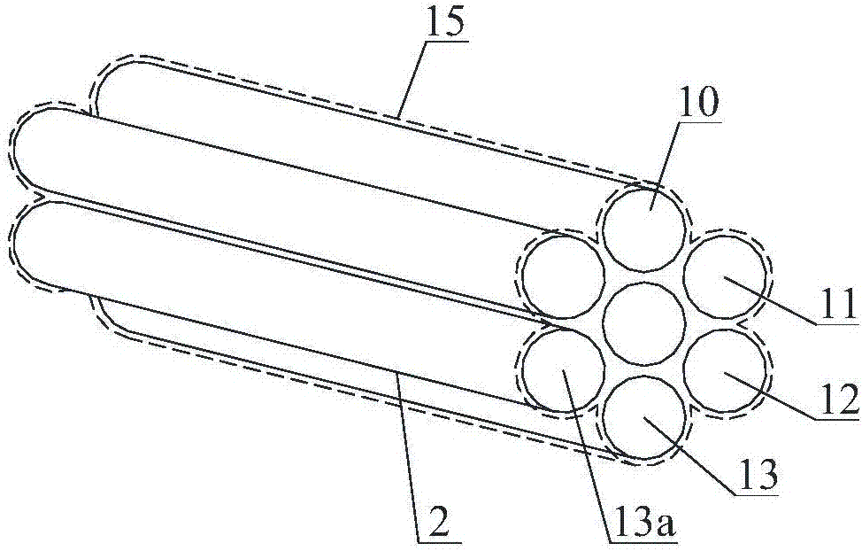
[0068] Such as Figure 1-7 As shown, the present embodiment describes a system using compressed air as the force source, which is characterized in that it includes a compressed air jet engine 14 using high-pressure and ultra-high-pressure compressed air (hereinafter referred to as compre...


PUM


Abstract

The invention provides a system taking compressed air as a force applying source. The system comprises a compressed air jet engine (14) which takes high-pressure and ultrahigh-pressure compressed air as a jet working medium, a compressed air production and supply device (48) for greatly producing, storing and supplying high-pressure and ultrahigh-pressure compressed air in an economic and environment-friendly manner and a controller, wherein the compressed air jet engine (14) is arranged on aviation, aerospace and navigation equipment such as airplanes, rockets, submarines, trains and the like as well as moving carriers which travel on the ground; the compressed air jet engine (14) comprises an air tank (9) used for storing the compressed air and a jet engine (16) used for generating power; the jet engine (16) comprises a primary jet engine (14) for generating thrust and a plurality of secondary jet engines for reducing air (or seawater) resistance as well as air (or seawater) sliding friction force generated in travelling of the moving carriers, so as to be beneficial for increasing the speed and saving energy, as well as increasing lifting force of wings of the airplane, so as to be beneficial for short-distance or vertical take-off, landing and the like of the airplane.

Description

technical field [0001] The invention relates to the technical field of engines, and in particular provides a system using compressed air as a force source, a method thereof, and an aircraft. Background technique [0002] Engine (Engine), that is, engine, is a machine that can convert other forms of energy into mechanical energy. It was born in England and has experienced the development stages of external combustion engine and internal combustion engine. The fuel of an external combustion engine is burned outside the engine, such as a steam engine; the fuel of an internal combustion engine is burned inside the engine, such as a gasoline engine, a diesel engine, and a jet engine. In fact, regardless of whether it is burned outside or inside the engine, the effect of combustion is to generate "high temperature and high pressure" gas in the engine; analyzing the direct effects of "high temperature" and "high pressure", people in the industry know that the effect of "high temper...

Claims


Application Information

Patent Timeline
Patent Type & Authority Patents(China)
IPC IPC(8): F02C1/02B64D27/16
CPCB64D27/16F02C1/02F05D2210/12
Inventor 王力丰
Owner 王力丰
Learn More