A method and system for an integrated decarburization device for a secondary reheat unit

A technology of double reheating and decarburization, which is applied in the direction of steam engine devices, separation methods, chemical instruments and methods, etc., can solve the problems of weakening the thermal economy of the overall system, small pressure difference of small turbines, and low efficiency of small turbines, and achieves Improve thermal economy, high pressure difference, and meet the effect of continuous operation

Active Publication Date: 2017-08-25
NORTH CHINA ELECTRIC POWER UNIV (BAODING)
View PDF1 Cites 0 Cited by
  • Summary
  • Abstract
  • Description
  • Claims
  • Application Information

AI Technical Summary

Problems solved by technology

The problem of this technology is: the decarburization device adopts intermittent operation mode. When the unit is in the decarburization condition, due to the mismatch between the steam flow and the structure of the low-pressure cylinder, the second-stage low-pressure cylinder needs to be disconnected from the main shaft, which reduces the unit’s capacity. Contribute
In addition, the steam source of the small turbine comes from the exhaust steam of the medium-pressure cylinder, and the pressure difference between the steam required by the decarburization device is low, and the steam flow rate is large, resulting in a small pressure difference between the inlet and outlet of the small turbine and a large flow rate, resulting in The low efficiency of the small turbine weakens the thermal economy of the overall system

Method used


Image

  • A method and system for an integrated decarburization device for a secondary reheat unit
  • A method and system for an integrated decarburization device for a secondary reheat unit
  • A method and system for an integrated decarburization device for a secondary reheat unit

Examples


Embodiment Construction

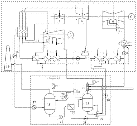
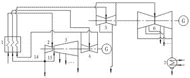
[0022] The invention introduces the decarburization device into the secondary reheating unit, and organically combines the secondary reheating technology and the decarburization technology. The boiler exhaust gas of the double reheating unit is sent to the decarburization device for decarbonization and then discharged from the chimney. The present invention is provided with a decarbonization steam turbine, and the decarbonization steam turbine uses the exhaust steam of the ultra-high pressure cylinder of the secondary reheating unit to do work, and the exhaust steam of the decarbonization steam turbine enters the reboiler in the decarbonization device for the regeneration of the carbon absorbent. The invention divides the exhaust steam of the ultra-high pressure cylinder of the double reheating unit into two parts or three parts. When the exhaust steam of the ultra-high pressure cylinder is divided into two parts: one part is sent to the boiler for primary reheating, and the ot...


PUM


Abstract

The invention provides a method and system for integrating a secondary reheating unit with a decarburization device. A decarburization steam turbine for providing a gas source for the decarburization device is set up, and exhaust steam of an ultrahigh pressure cylinder of the secondary reheating unit is divided into two parts or three parts; when the exhaust steam of the ultrahigh pressure cylinder is divided into two parts, one part of the exhaust steam is supplied into a boiler to be subjected to primary reheating, and the other part of the exhaust steam is supplied into the decarburization steam turbine; when the exhaust steam of the ultrahigh pressure cylinder is divided into three parts, the first part of the exhaust steam enters a high-pressure heater to heat supplied water, the second part of the exhaust steam is supplied into a hot boiler to be subjected to primary reheating, and the third part of the exhaust steam is supplied to the decarburization steam turbine; the exhaust steam pressure of the ultrahigh pressure cylinder ranges from 8 MPa to 13 MPa, and the exhaust steam pressure of the decarburization steam turbine ranges from 0.2 MPa to 0.4 MPa. The differential pressure of the decarburization steam turbine is high, the flow is large, high efficiency is guaranteed, and the continuous operating requirement of the decarburization device can be met. Part of the exhaust steam of the decarburization steam turbine is supplied to the high-pressure heater, and part of the exhaust steam of the decarburization steam turbine is supplied to a low-pressure heater, greater irreversible damage caused by exhaust steam supply of a high-pressure cylinder and a medium-pressure cylinder is avoided, and the heat economy of the whole system is improved.

Description

technical field [0001] The invention relates to a method and a system for integrating a decarburization device with a thermal power unit for thermal power generation, especially a double reheat unit. Background technique [0002] In the "Twelfth Five-Year Plan", my country has specified the goal of reducing carbon emission intensity by 16%-17%. 2 The contribution rate of emissions is up to 50%, so if you want to reduce CO 2 emissions, thermal power units will inevitably bear the brunt of emissions reduction. The use of high-parameter secondary reheat technology can improve the efficiency of thermal power units and reduce coal consumption for power generation, thereby reducing CO 2 emissions, but if more CO emissions are to be reduced 2 , an additional decarburization device is required. In the prior art, the decarbonization device consumes a lot of energy and cannot be simply added at the end of the unit like the desulfurization device. At present, there is a way to com...

Claims


Application Information

Patent Timeline
Patent Type & Authority Patents(China)
IPC IPC(8): F01K17/00F01K11/02B01D53/14F23J15/00
CPCB01D53/1425B01D53/1475F01K11/02F01K17/00F23J15/006Y02E20/32
Inventor 付文锋王蓝婧李嘉华杨勇平
Owner NORTH CHINA ELECTRIC POWER UNIV (BAODING)
Why Eureka
Try Eureka