
Rack end protection method

An end protection and rack technology, which is applied in the control field of electric power steering system, can solve the problems of no change in hand feel, poor control feeling, and insufficient smooth hand feel, so as to save material costs, improve handling experience, and save processes and time. cost effect

Active Publication Date: 2018-02-23
LIANCHUANG AUTOMOBILE ELECTRONICS
View PDF5 Cites 1 Cited by
  • Summary
  • Abstract
  • Description
  • Claims
  • Application Information

AI Technical Summary

Problems solved by technology

The problem with this existing method of realizing the rack end protection function through the electric power steering system is that the feel is not smooth enough. For example, fast steering and slow steering 11 are two different operating conditions. The protection area at the end does not distinguish between the two operating conditions, the specific performance is that there is no change in the hand feel and the control experience is not good

Method used


Image

  • Rack end protection method
  • Rack end protection method
  • Rack end protection method

Examples


Embodiment Construction

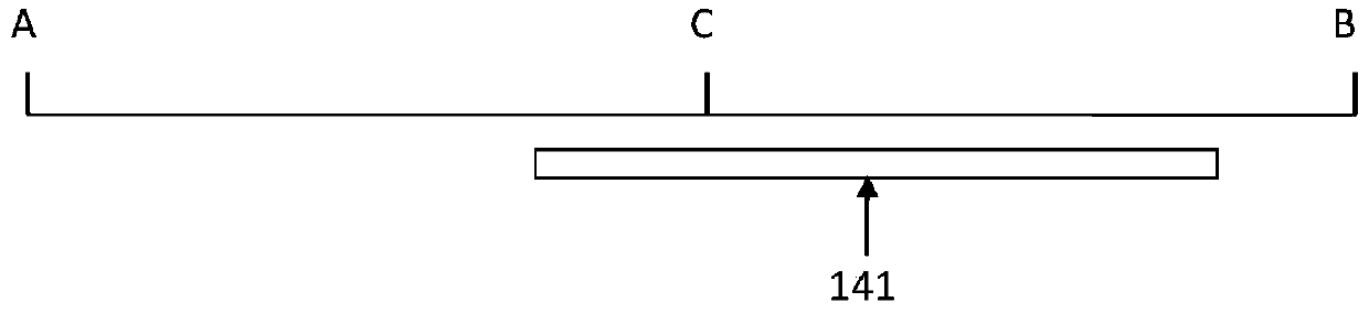
[0030] The rack end protection method of the present application is realized by a control method of an electric power steering system. see Figure 5, set the starting point M of the left protection area at the Y length from the end A of the left rack, and the left protection area is between the two points M and A. Set the starting point N of the right protection area at the Y length from the end B of the right rack, and the right protection area is between the two points N and B. When any end of the rack 141 enters any protected area, it indicates that the rack 141 moves close to the end position of the rack on this side, that is, the steering wheel 11 rotates to the maximum angle close to a certain direction of rotation, that is, the position on the other side. The ball head 144 moves closer to the other end of the housing 140 . At this time, by reducing the boost torque output by the boost motor 24 (it can be reduced to zero or a negative number), the resistance torque tha...


PUM


Abstract

This application discloses a rack end protection method. Protection areas are set at both ends of the rack. Once either end of the rack enters any protection area, the assist torque output by the electric power steering system is reduced; the reduction of the assist torque is It is directly proportional to the distance between the end of the rack entering the protection area and the starting point of the protection area, and also proportional to the displacement speed of the rack. This application can significantly improve the driver's control experience in both fast and slow steering conditions.

Description

technical field [0001] The present application relates to a method for controlling an electric power steering system of an automobile, in particular to a method for using the electric power steering system to protect the end of a rack. Background technique [0002] see figure 1 , The mechanical steering system on the car mainly includes a steering wheel 11, a steering column 12, an intermediate shaft 13, a steering gear 14, a steering tie rod 15, a steering knuckle arm 16 and a steering wheel 17. The steering gear 14 is a rack-and-pinion steering gear with a rack 141 and a pinion 142 built in. When the driver turns the steering wheel 11 , the steering shaft built in the steering column 12 is driven to rotate, and the steering shaft is connected with the pinion 142 through the intermediate shaft 13 . The pinion 142 meshes with the rack 141 to drive the rack 141 to move leftward or rightward in the steering gear 14 . The rack 141 is rigidly connected with the tie rod 15, so...

Claims


Application Information

Patent Timeline
Patent Type & Authority Patents(China)
IPC IPC(8): B62D5/04B62D3/12B62D6/00B62D113/00B62D117/00B62D119/00
Inventor 李若飞施雯金灿龙郑鸿云陈笑建
Owner LIANCHUANG AUTOMOBILE ELECTRONICS
Learn More