Radiating type power distribution cabinet with illumination function
A heat-dissipating, power distribution cabinet technology, applied in electrical components, substation/switch layout details, substation/switchgear cooling/ventilation, etc. problem, to achieve the effect of stable resistance, easy installation and reduction of contact resistance
- Summary
- Abstract
- Description
- Claims
- Application Information
AI Technical Summary
Problems solved by technology
Method used
Image
Examples
Embodiment 1
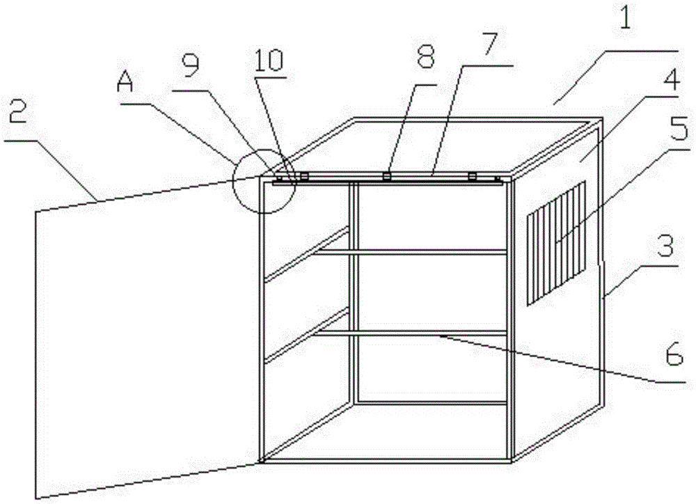
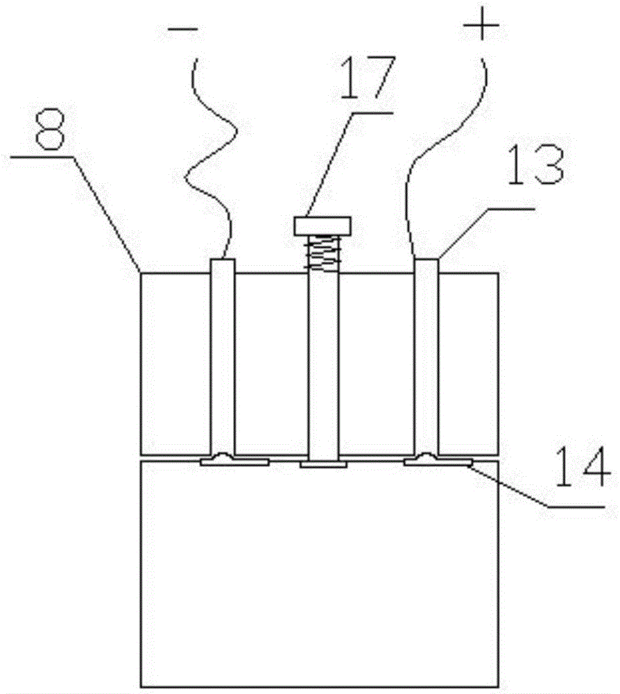
[0043] Such as figure 1As shown, a heat dissipation power distribution cabinet with lighting function includes a cabinet body 1 and a cabinet door 2. The cabinet body 1 is composed of a frame 3 and a cabinet panel 4. The cabinet door 2 and the cabinet body 1 are connected by a rotating shaft type living hinge; There are cooling windows 5 on the side of the cabinet body 1; there is also a fixed beam 6 inside the cabinet body 1, and the fixed beam 6 is located in the middle of the frame 3 and is fixedly connected with the frame 3; 7. A fixed joint 8 is provided in the length direction. The fixed joint 8 has a power interface inside. The cabinet edge 7 is provided with hooks 9 at least on both sides. The fixed joint is connected with a lighting device 10. Such as figure 2 As shown, the lighting device 10 is in the shape of a strip, and the lighting device 10 has a hanging ring 11 at a position corresponding to the hook of the cabinet edge 7, and a pressing handle 12 is provided...
Embodiment 2
[0053] refer to figure 1 As shown, a heat dissipation power distribution cabinet with lighting function includes a cabinet body 1 and a cabinet door 2. The cabinet body 1 is composed of a frame 3 and a cabinet panel 4. The cabinet door 2 and the cabinet body 1 are connected by a rotating shaft type living hinge; There are cooling windows 5 on the side of the cabinet body 1; there is also a fixed beam 6 inside the cabinet body 1, and the fixed beam 6 is located in the middle of the frame 3 and is fixedly connected with the frame 3; 7. A fixed joint 8 is provided in the length direction. The fixed joint 8 has a power interface inside. The cabinet edge 7 is provided with hooks 9 at least on both sides. The fixed joint is connected with a lighting device 10. Such as figure 2 As shown, the lighting device 10 is in the shape of a strip, and the lighting device 10 has a hanging ring 11 at a position corresponding to the hook of the cabinet edge 7, and a pressing handle 12 is provid...
Embodiment 3
[0056] refer to figure 1 As shown, a heat dissipation power distribution cabinet with lighting function includes a cabinet body 1 and a cabinet door 2. The cabinet body 1 is composed of a frame 3 and a cabinet panel 4. The cabinet door 2 and the cabinet body 1 are connected by a rotating shaft type living hinge; There are cooling windows 5 on the side of the cabinet body 1; there is also a fixed beam 6 inside the cabinet body 1, and the fixed beam 6 is located in the middle of the frame 3 and is fixedly connected with the frame 3; 7. A fixed joint 8 is provided in the length direction. The fixed joint 8 has a power interface inside. The cabinet edge 7 is provided with hooks 9 at least on both sides. The fixed joint is connected with a lighting device 10. The structures and functions of other components are the same as in Embodiment 1. The difference with embodiment 1 is: as Figure 7 As shown, there are 6 copper tubes 13, which are arranged equidistantly along the circumfere...
PUM
 Abstract
Description
Claims
Application Information
 - R&D
- Intellectual Property
- Life Sciences
- Materials
- Tech Scout
- Unparalleled Data Quality
- Higher Quality Content
- 60% Fewer Hallucinations
Browse by: Latest US Patents, China's latest patents, Technical Efficacy Thesaurus, Application Domain, Technology Topic, Popular Technical Reports.
© 2025 PatSnap. All rights reserved.Legal|Privacy policy|Modern Slavery Act Transparency Statement|Sitemap|About US| Contact US: help@patsnap.com


