
Rotor oil pump

A rotor oil pump and oil pump technology, which is applied to lubricating pumps, mechanical equipment, engine components, etc., can solve problems such as large gas content in engine oil, air inhalation at the oil suction port, damage to bearing bushes, and hydraulic tappet components, etc., to reduce engine oil. Effect of air content, reduction of friction loss, and reduction of sticking phenomenon

Inactive Publication Date: 2016-06-01
CHERY AUTOMOBILE CO LTD
View PDF6 Cites 6 Cited by
  • Summary
  • Abstract
  • Description
  • Claims
  • Application Information

AI Technical Summary

Problems solved by technology

[0007] On the one hand, at present, many oil pumps are installed and matched through the positioning pin of the oil pump, but for the oil pump directly installed on the crankshaft, since the rotor shaft in the oil pump is driven by the crankshaft, this will cause over-positioning of the oil pump , so that the oil pump cannot work normally, and in serious cases, it will cause excessive wear, abnormal noise or even scrapping of the oil pump
[0008] In addition, at present, for the oil pump directly driven by the crankshaft, because it is installed at the front end of the crankshaft, especially because the oil level away from the oil pan is very high, and the flatness of the end surface where the oil pump is installed is not good, there are large deformation factors. Therefore, it is easy to cause air to be sucked into the oil suction port. This problem will cause the engine oil to contain too much air, the system pressure will be low, and it will cause fatal damage to bearing bushes, hydraulic tappets and other components.
Therefore, it is very important to control the gas content of the oil pump oil, but the oil pump cavity of the prior art lacks effective measures for the control of this problem

Method used


Image

  • Rotor oil pump
  • Rotor oil pump
  • Rotor oil pump

Examples


Embodiment Construction

[0031] The specific implementation of the present invention will be described in further detail below by describing the embodiments with reference to the accompanying drawings, so as to help those skilled in the art have a more complete, accurate and in-depth understanding of the inventive concepts and technical solutions of the present invention.

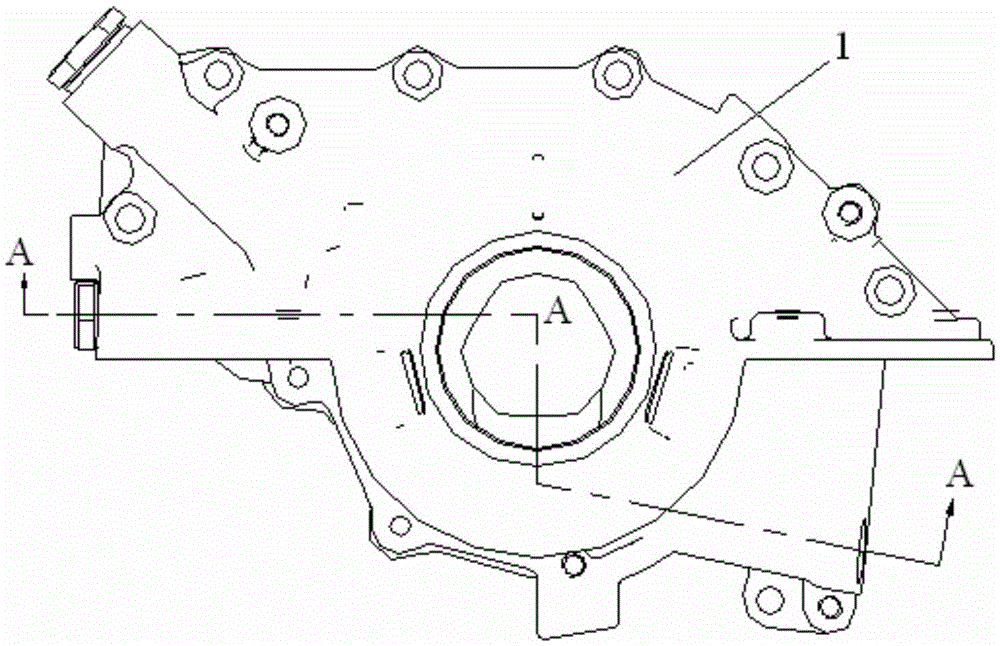
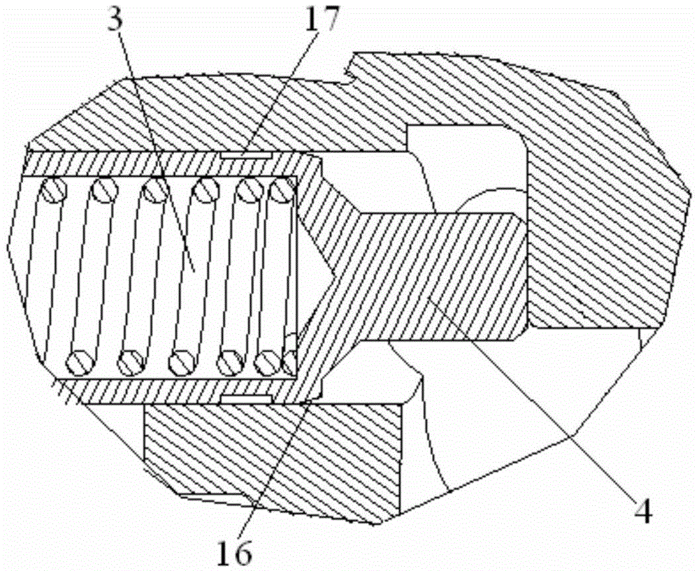
[0032] Such as figure 1 , figure 2 The structure of the present invention expressed is a rotor oil pump, including an oil pump housing 1 , an inner rotor 7 , and an outer rotor 8 . The oil pump housing 1 is provided with an oil inlet 5 and an oil outlet 12 . The inner rotor 7 and the outer rotor 8 are arranged in the cavity formed by the oil pump cover plate 6 and the oil pump housing 1 .

[0033] The rotor oil pump is fastened and installed by cross-recessed bolts 13 .

[0034] In order to solve the problems existing in the prior art and overcome its defects, realize the invention purpose of reducing the friction loss of the en...


PUM


Abstract

The invention discloses a rotor oil pump. The rotor oil pump comprises an oil pump shell (1), an inner rotor (7) and an outer rotor (8). The oil pump shell (1) is provided with an oil inlet (5) and an oil outlet (12). An inner hole, matched with a crankshaft, of the oil pump shell (1) is provided with three evenly-distributed protrusions facing the center of the inner hole, and a three-jaw structure (9) is formed. The top faces of the three protrusions are in sliding fit with the crankshaft. By means of the technical scheme, the cost of an engine can be effectively reduced; the friction loss of the engine is effectively reduced; the air content of oil of the engine is effectively reduced; the stuck phenomenon of a valve element of a pressure limiting valve due to dirt is reduced; in addition, the stability of a spring of the pressure limiting valve is good; and the sealing performance of the oil outlet is good.

Description

technical field [0001] The invention belongs to the technical field of engine lubricating systems, and in particular relates to a rotor oil pump. Background technique [0002] When the engine is working, friction will inevitably occur between the relative moving surfaces of the transmission parts (such as the crankshaft and the main bearing, the piston and the cylinder wall, the timing gear pair, the gas distribution system, etc.). The friction between the metal surfaces will not only increase the power consumption inside the engine and cause the working surface of the parts to wear out rapidly, but also the large amount of heat generated by the friction may cause the working surface of the parts to burn, making the engine unable to run. In order to ensure the long-term and reliable operation of the machine, sufficient lubricating oil must be delivered to these surfaces in time through the lubrication system during operation. The function of the lubrication system is to con...

Claims


Application Information

Patent Timeline
Patent Type & Authority Applications(China)
IPC IPC(8): F16N13/20F16N23/00
CPCF16N13/20F16N23/00F16N2280/00
Inventor 倪伟古春山李亚南张欣林
Owner CHERY AUTOMOBILE CO LTD
Learn More