A Top Entry Axial Flow Check Valve

A technology for check valves and valve seats, which is applied in the direction of control valves, valve devices, and functional valve types. flow effect

Active Publication Date: 2018-08-28
杨恒
View PDF5 Cites 0 Cited by
  • Summary
  • Abstract
  • Description
  • Claims
  • Application Information

AI Technical Summary

Problems solved by technology

At present, the installation of the check valve on the pipeline is to install the relevant parts from the side, and then weld it on the delivery pipeline; when the internal parts of the check valve need to be repaired, they can only be repaired after being cut off from the pipeline. Therefore, the maintenance method is relatively difficult, and it also causes great troubles to the operation of the pipeline.

Method used


Image

  • A Top Entry Axial Flow Check Valve
  • A Top Entry Axial Flow Check Valve
  • A Top Entry Axial Flow Check Valve

Examples


Embodiment 1

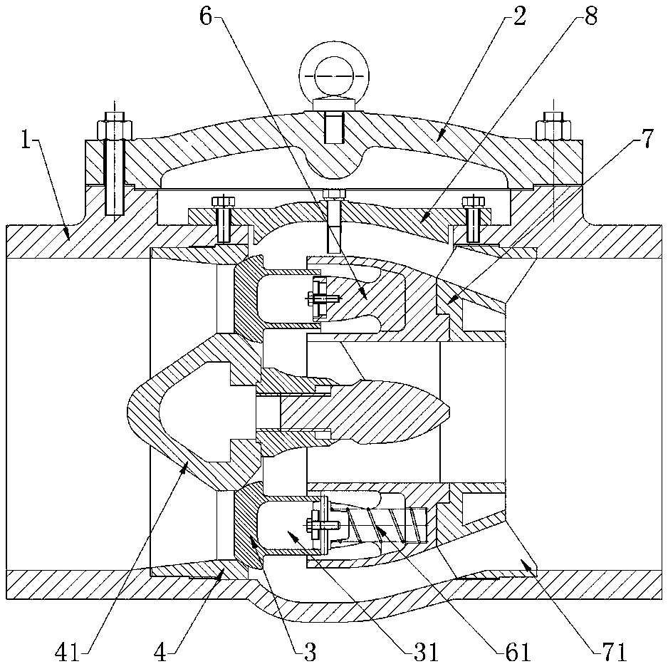
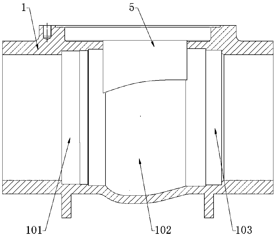
[0021] See figure 1 with figure 2 , Top-mounted axial flow check valve, including valve body 1, valve disc 3, valve seat 4 and valve cover 2. The valve body 1 is opened with a maintenance hole 5, and the maintenance hole 5 is covered with a valve cover 2; The internal distribution is a medium inlet 101, a valve cavity 102 and a medium outlet 103; a valve seat 4 is fixed at the medium inlet 101, and the valve seat 4 is a ring structure. The center of the valve seat 4 is provided with a valve seat guide 41, the valve seat The guide head 41 has a tapered structure; the valve seat 4 is softly connected to the valve disc 3 at the back of the medium inlet 101, that is, the valve disc 3 and the valve seat 4 are not in a fixed connection relationship. When the check valve is closed, the valve disc 3 and The valve seat 4 is connected in a sealed manner by the sealing surface between each other, and when the check valve is open, the valve disc 3 and the valve seat 4 are in a separated st...

Embodiment 2

[0024] See figure 1 This embodiment is an improvement of the first embodiment, that is, under the valve cover 2 and at the maintenance hole 5, a fairing 8 with a streamlined structure is provided, and the inner surface of the corresponding valve body 1 has a streamlined structure.

[0025] See Figure 4 , Due to the increase of the fairing, the flow of the medium is changed from turbulent flow to orderly flow, which can effectively reduce the generation of noise.

Embodiment approach 3

[0027] This embodiment is another improvement of the first embodiment. The fixed connection between the valve seat and the valve body is sealed by a two-way spring energy storage sealing ring.

[0028] The two-way spring energy storage sealing ring provides longitudinal sealing in the medium conveying direction (horizontal), and when the medium returns, it provides transverse sealing; thereby providing lasting elasticity, and at the same time, it can make up for the gap generated during low-temperature cold shrinkage.


PUM


Abstract

The invention provides an upper-portion-mounted axial flow check valve. The upper-portion-mounted axial flow check valve comprises a valve body and a valve deck, wherein the valve body is provided with a maintenance hole which is covered with the valve deck; a medium inlet, a valve cavity and a medium outlet are distributed inside the valve body; a valve seat is fixed at the medium inlet; a valve seat flow guide head is arranged in the center of the valve seat; the position, at the back of the medium inlet, of the valve seat is in soft connection with valve clacks; a spring annular groove is formed in the side, at the back of the medium inlet, of each valve clack and movably connected with a spring frame; each spring frame and the outer surface of a connecting protruding block of the corresponding valve clack are sleeved with a spring; a supporting frame is fixedly connected with the side, facing the medium outlet, of each spring frame and fixed to the medium outlet; each supporting frame is of an annular structure and evenly provided with leakage holes. The valve body is provided with the maintenance hole, so that related assemblies are taken out and repaired, and then on-line rapid maintenance is achieved. The upper-portion-mounted axial flow check valve can be widely used for conveying media from high temperature to low temperature by changing the manufacturing materials of the check valve.

Description

Technical field [0001] The invention belongs to the field of check valves and relates to online maintenance technology of check valves, in particular to a top-mounted axial flow check valve. Background technique [0002] The axial flow check valve is a check valve that determines the opening of the disc and the pipe wall by the pressure difference between the inlet end and the outlet end. At present, the installation of check valves on the pipeline is to install the relevant parts from the side, and then weld them to the conveying pipeline; when the internal parts of the check valve need to be repaired, the repair can only be performed after cutting off the pipeline. Therefore, the maintenance method is more difficult, and the pipeline operation also caused great trouble. Summary of the invention [0003] The purpose of the present invention is to provide an axial flow check valve that can realize online maintenance, which can maintain the components in the check valve through a ...

Claims


Application Information

Patent Timeline
Patent Type & Authority Patents(China)
IPC IPC(8): F16K15/02
Inventor 杨恒
Owner 杨恒
Why Eureka
Try Eureka