Eureka AIR delivers breakthrough ideas for toughest innovation challenges, trusted by R&D personnel around the world.

Automatic positioning code printer

An automatic positioning and coding technology, applied in the direction of power transmission device, printing device, printing, etc., can solve the problems of wrong material use, chaotic operation, low position accuracy, etc. The effect of reducing labor intensity

Pending Publication Date: 2016-06-01
苏州圣瑞赛标识科技有限公司
View PDF9 Cites 8 Cited by
  • Summary
  • Abstract
  • Description
  • Claims
  • Application Information

AI Technical Summary

Problems solved by technology

The way of using the printing wheel has the following disadvantages: (1) The color of the printing is relatively light, and it is not clear after vulcanization; (2) The surface of the crown layer has a shape, and large characters cannot be printed; (3) The printing is unclear before vulcanization, and it is easy to cause tire blank Wrong vulcanization mold; (4) When each model is replaced, the printing mold needs to be replaced, which increases the load on the staff; (5) The printing is easy to replace and wrong (materials may also be used wrong); (6) The printing mold and scraper are easy to deform, It needs to be replaced regularly; (7) Ghosting is easy to appear after printing and vulcanization
The method of using manual coding has the following disadvantages: (1) input information errors are prone to occur; (2) the moving method is inconvenient and manual movement is required; (3) the coordinate positions of each specification are different, which is easy to cause confusion in operation; ( 4) The positioning process requires manual measurement, and the position accuracy is low
The device belongs to the manual coding method, and has the disadvantages of the above-mentioned manual coding method

Method used


Image

  • Automatic positioning code printer
  • Automatic positioning code printer
  • Automatic positioning code printer

Examples


Embodiment 1

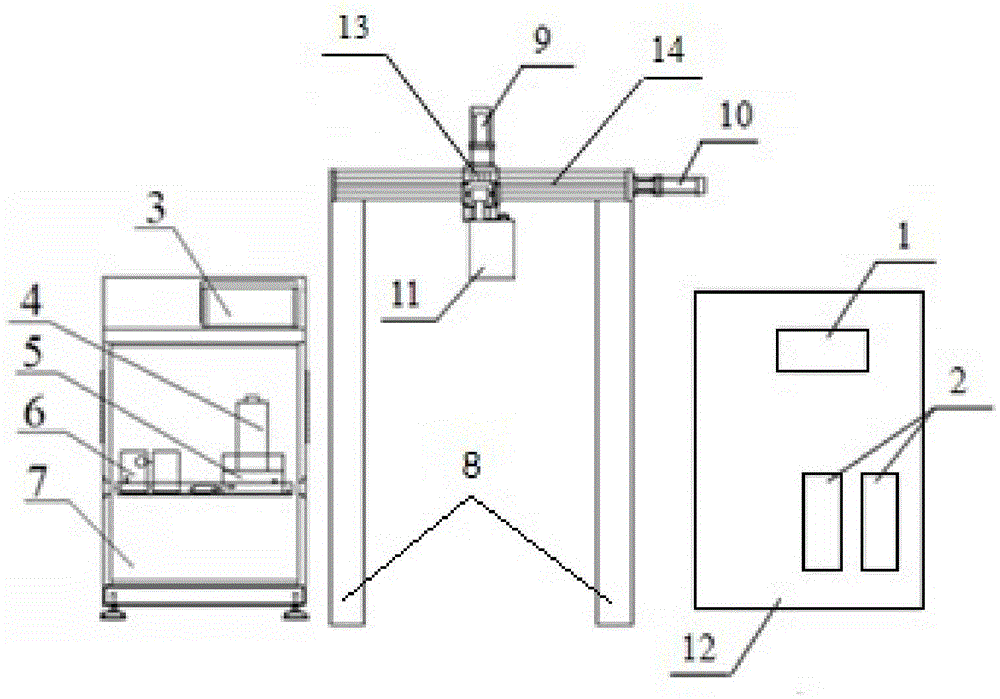
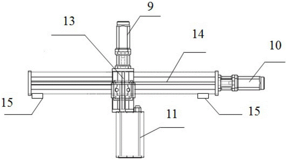
[0032] An automatic positioning inkjet device, such as figure 1 As shown, it includes a frame 8, a control assembly, an ink supply assembly, a nozzle 11 and a nozzle moving assembly. The nozzle 11 and the nozzle moving assembly are respectively connected to the control assembly. The transmission mechanism is arranged on the frame 8, the Y-axis transmission mechanism is arranged on the X-axis transmission mechanism, and the nozzle 11 is arranged on the Y-axis transmission mechanism. Limiter, a photoelectric switch for sensing the product to be coded, a code control photoelectric switch for controlling the opening and closing of the nozzle, and a distance sensing photoelectric switch for controlling the distance between the nozzle and the product to be coded.

[0033] Wherein, the X-axis transmission mechanism includes the first lead screw 14 and the first servo motor 10 that controls the rotation of the first lead screw 14, the first lead screw 14 is rotatably connected with th...


PUM


Abstract

The present invention relates to an automatic positioning code printer. The automatic positioning code printer comprises a frame, an ink supply assembly, a nozzle, a control assembly and a nozzle mobile assembly. The nozzle and the nozzle mobile assembly are connected with the control assembly; the nozzle mobile assembly includes an X-axis transmission mechanism and a Y-axis transmission mechanism; the X-axis transmission mechanism is arranged on the frame, the Y-axis transmission mechanism is arranged on the X-axis transmission mechanism, and the nozzle is installed on the Y-axis transmission mechanism. Compared with the prior art, the automatic positioning code printer is simple in structure, clear in printing, is able to print large characters and rapidly adapt the specifications of products with various printing codes, is accurate in printing code positioning, and greatly reduce the operators' labor intensity, etc.

Description

technical field [0001] The invention relates to a coding device, in particular to an automatic positioning coding device. Background technique [0002] During the tire manufacturing process, the type or code of the tire used must be marked on the extruded semi-finished product to facilitate subsequent engineering use and finished product marking. [0003] At present, various tire manufacturers generally use printing wheels or manual coding methods. The way of using the printing wheel has the following disadvantages: (1) The color of the printing is relatively light, and it is not clear after vulcanization; (2) The surface of the crown layer has a shape, and large characters cannot be printed; (3) The printing is unclear before vulcanization, and it is easy to cause tire blank Wrong vulcanization mold; (4) When each model is replaced, the printing mold needs to be replaced, which increases the load on the staff; (5) The printing is easy to replace and wrong (materials may al...

Claims


Application Information

Patent Timeline
Patent Type & Authority Applications(China)
IPC IPC(8): B41J3/407B41J2/01B41J29/393B41J25/24
CPCB41J2/01B41J3/4073B41J25/24B41J29/393
Inventor 车传伟
Owner 苏州圣瑞赛标识科技有限公司
Why Eureka
Eureka Blog
Learn More