Pressurized self-balancing grinding machine with ultra-large rolls
A self-balancing and super large technology, applied in grain processing and other directions, it can solve the problems of low efficiency, low output, and less biting materials, and achieve the effect of high efficiency, high output and ingenious structure.
- Summary
- Abstract
- Description
- Claims
- Application Information
AI Technical Summary
Problems solved by technology
Method used
Image
Examples
Embodiment 1
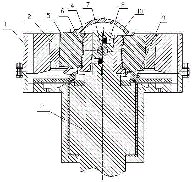
[0020] Such as image 3 As shown, the pressurized self-balancing ultra-large roller mill of the present invention includes a machine base 1 and a grinding ring 2 arranged on the machine base 1. A grinding roller part is arranged in the grinding ring 2, and the grinding roller part passes through the The central rotor 3 at the center of the machine base 1 is driven to work. In order to improve the working efficiency and output of the mill, the grinding roller parts of the present invention are made of an inner grinding roller 4 and an outer grinding roller 5. The inner grinding roller 4 and the outer grinding roller A rotating bearing 6 is arranged between the joint surfaces of the outer grinding rollers 5. During actual manufacture, the rotating bearing 6 can be a sliding bearing or a rolling bearing; the central rotor 3 located in the center hole of the inner grinding roller 4 is provided with a shaft hole horizontally. The two ends of the rotary shaft 7 pierced in the shaft ...
Embodiment 2
[0023] If the central rotor in embodiment 1 is changed as Figure 4 The structure shown, that is, the central rotor is composed of a fixed jacket 3.1 and a swing rod 3.2 placed inside it. The swing rod 3.2 is connected to the lower end of the fixed jacket 3.1 through a hinge shaft 11, and the shaft hole is opened at the center of the inner grinding roller 4 On the swing rod 3.2 in the hole, the two ends of the rotary shaft 7 slidingly penetrated in the shaft hole extend to the side wall of the inner grinding roller and are fixedly connected with it as a whole. The swing rods located at the upper and lower positions of the rotary shaft 7 are symmetrically staggered Inner grinding roller thrust devices 8 are respectively arranged in the opened blind holes.
[0024] In the present invention, the center rotor is changed to be composed of a fixed outer sleeve 3.1 and a swing rod 3.2 placed therein. When a large error occurs during manufacture or installation, its center of mass can...
PUM
 Abstract
Description
Claims
Application Information
 - Generate Ideas
- Intellectual Property
- Life Sciences
- Materials
- Tech Scout
- Unparalleled Data Quality
- Higher Quality Content
- 60% Fewer Hallucinations
Browse by: Latest US Patents, China's latest patents, Technical Efficacy Thesaurus, Application Domain, Technology Topic, Popular Technical Reports.
© 2025 PatSnap. All rights reserved.Legal|Privacy policy|Modern Slavery Act Transparency Statement|Sitemap|About US| Contact US: help@patsnap.com


