Pressurized self-balancing ultra-large roller mill

A self-balancing, super-large technology, applied in the direction of grain processing, etc., can solve the problems of low efficiency, less gnawing materials, and low output, and achieve the effect of high efficiency, ingenious structure, and high output

Active Publication Date: 2018-06-19
HENAN LIMING HEAVY IND SCI & TECH +1
View PDF9 Cites 0 Cited by
  • Summary
  • Abstract
  • Description
  • Claims
  • Application Information

AI Technical Summary

Problems solved by technology

The ring roller mill of this traditional structure has a simple structure, the grinding roller is empty on the shaft, and there is no bearing component. Due to friction, impact, etc., the grinding roller on the upper surface will produce huge noise in actual production

Method used


Image

  • Pressurized self-balancing ultra-large roller mill
  • Pressurized self-balancing ultra-large roller mill
  • Pressurized self-balancing ultra-large roller mill

Examples


Embodiment 1

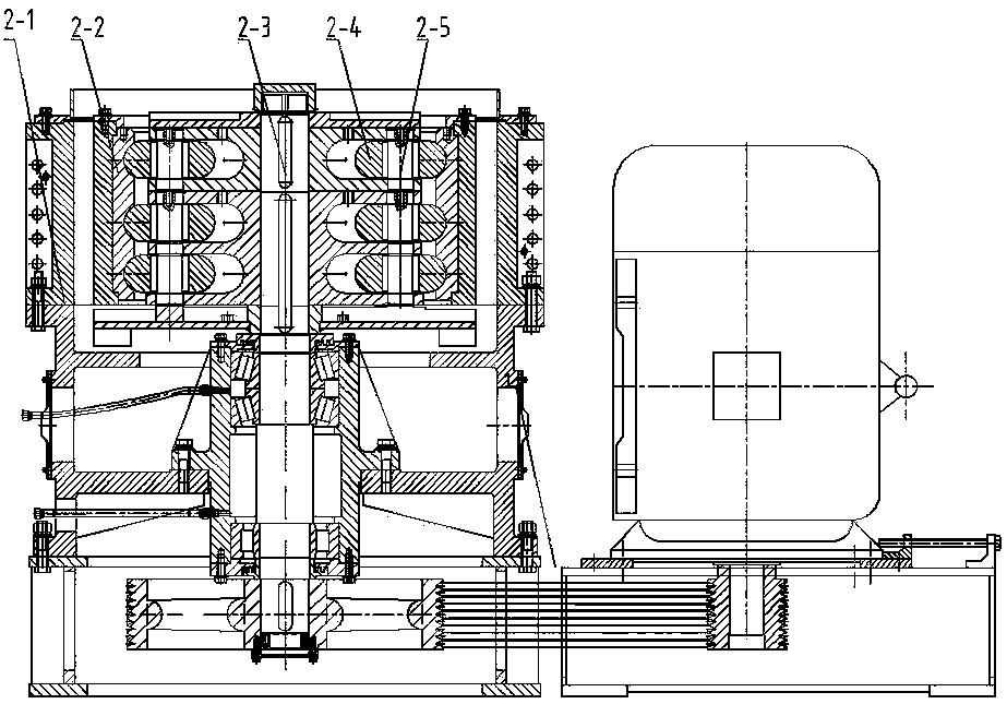
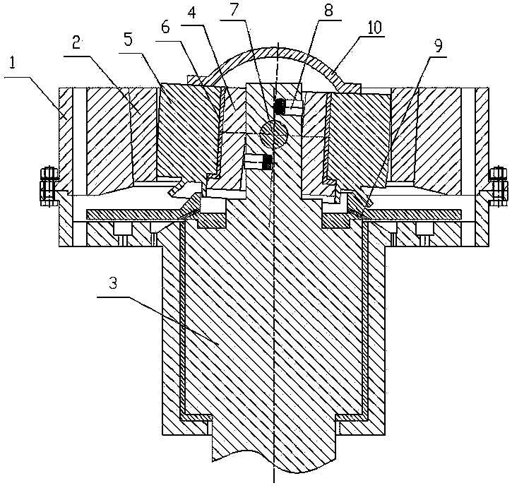
[0020] Such as image 3 As shown, the pressurized self-balancing ultra-large roller mill of the present invention includes a machine base 1 and a grinding ring 2 arranged on the machine base 1. A grinding roller part is arranged in the grinding ring 2, and the grinding roller part passes through the The central rotor 3 at the center of the machine base 1 is driven to work. In order to improve the working efficiency and output of the mill, the grinding roller parts of the present invention are made of an inner grinding roller 4 and an outer grinding roller 5. The inner grinding roller 4 and the outer grinding roller A rotating bearing 6 is arranged between the joint surfaces of the outer grinding rollers 5. During actual manufacture, the rotating bearing 6 can be a sliding bearing or a rolling bearing; the central rotor 3 located in the center hole of the inner grinding roller 4 is provided with a shaft hole horizontally. The two ends of the rotary shaft 7 pierced in the shaft ...

Embodiment 2

[0023] If the central rotor in embodiment 1 is changed to Figure 4 The structure shown, that is, the central rotor is composed of a fixed jacket 3.1 and a swing rod 3.2 placed inside it. The swing rod 3.2 is connected to the lower end of the fixed jacket 3.1 through a hinge shaft 11, and the shaft hole is opened at the center of the inner grinding roller 4 On the swing rod 3.2 in the hole, the two ends of the rotary shaft 7 slidingly penetrated in the shaft hole extend to the side wall of the inner grinding roller and are fixedly connected with it as a whole. The swing rods located at the upper and lower positions of the rotary shaft 7 are symmetrically staggered Inner grinding roller thrust devices 8 are respectively arranged in the opened blind holes.

[0024] In the present invention, the center rotor is changed to be composed of a fixed outer sleeve 3.1 and a swing rod 3.2 placed therein. When a large error occurs during manufacture or installation, its center of mass can...


PUM


Abstract

The invention discloses a pressurized self-balancing grinding machine with ultra-large rolls. The pressurized self-balancing grinding machine comprises a seat and a grinding ring arranged on the seat, wherein a grinding roll component is arranged in the grinding ring; the grinding roll component is driven to work through a central rotor arranged at the central position of the seat; the grinding roll component is composed of an inner grinding roll and an outer grinding roll in a sleeving manner; a rotary bearing is arranged between the combined surfaces of the inner grinding roll and the outer grinding roll; a shaft hole is horizontally formed in a central rotor located in a central hole of the inner grinding roll; the two ends of a rotary shaft arranged in the shaft hole in a penetrating manner extend to the sidewall of the inner grinding roll; and inner grinding roll thrust devices are arranged in blind holes which are symmetrically formed in central rotors located at an upper position and a lower position of the rotary shaft in a staggered manner respectively. The pressurized self-balancing grinding machine disclosed by the invention is ingenious and reasonable in structure, and gets rid of the design limit that the size of the grinding roll component of the grinding machine cannot be greater than 1 / 2 of the diameter of the grinding ring; the diameter of the grinding roll component theoretically can be close to the dimension of the inner diameter of the grinding ring; and compared with the traditional structure, the grinding roll component with an ultra-large structure is capable of achieving much engaging-in of materials, high in efficiency, and high in yield.

Description

technical field [0001] The invention relates to a ring roller mill or a Raymond mill, in particular to a pressurized self-balancing ultra-large roller mill. Background technique [0002] Currently commonly used mills include suspension roller mills (or called Raymond mills) and ring roller mills (or called three-ring mills). The main structure of the suspension roller mill is as follows: figure 1 As shown, it includes a machine base 1-1, a grinding ring 1-2 installed on the machine base 1-1, a rolling device with grinding rollers 1-3 arranged in the main machine, and a working shaft 1 located at the center of the main machine -4 Turn and drive the grinding roller 1-3 of the rolling device to press against the grinding ring, and roll the material between the grinding ring 1-2 and the grinding roller 1-3. From figure 1 It can be seen from the figure that the diameter of the grinding rollers 1-3 on the rolling device cannot exceed 1 / 2 of the diameter of the grinding ring due...

Claims


Application Information

Patent Timeline
Patent Type & Authority Patents(China)
IPC IPC(8): B02C15/06
CPCB02C15/06
Inventor 郝身峙宁晋
Owner HENAN LIMING HEAVY IND SCI & TECH
Why Eureka
Try Eureka