
Seismic identification method for complex fault block unconformity surfaces

A technology for complex fault block and seismic identification. It is applied in seismology and seismic signal processing for logging records. It can solve the problems of complex upper and lower lithology, complex structural morphology, and difficulty in horizon calibration, and achieve accurate identification. , the economic and social benefits are significant, and the effect of promotion and application is broad.

Inactive Publication Date: 2016-05-25
CHINA PETROLEUM & CHEM CORP +1
View PDF5 Cites 7 Cited by
  • Summary
  • Abstract
  • Description
  • Claims
  • Application Information

AI Technical Summary

Problems solved by technology

Due to the in-depth exploration and development, some unconformity reservoirs with simple structural forms have a higher degree of exploitation, the identification of unconformity surfaces is relatively simple, and the understanding and description are also very fine. characteristics, restricting its understanding of oil reservoirs and oil and gas development
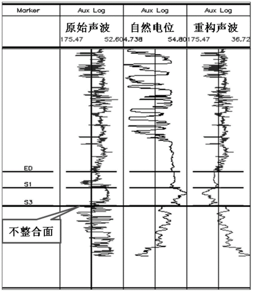
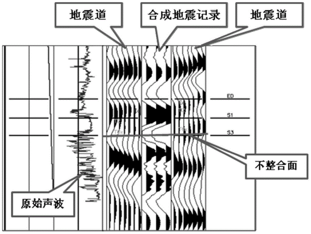
The existing seismic description of unconformity is mainly based on the horizontal calibration of acoustic wave synthesis records through the wave group characteristics of the unconformity's upper and lower reflection coaxial axes. Velocity changes are large, faults are developed, and seismic resolution is limited. Seismic profiles cannot effectively reflect the shape of unconformities. Due to denudation or overlapping of unconformities, the upper and lower lithologies are complex. Conventional synthetic records and side-hole seismic The trace matching effect is poor, the horizon calibration near the unconformity is difficult, and the seismic description of the unconformity is difficult. Therefore, we invented a seismic identification method for the unconformity in complex fault-block reservoirs, which solved the above problems

Method used


Image

  • Seismic identification method for complex fault block unconformity surfaces
  • Seismic identification method for complex fault block unconformity surfaces
  • Seismic identification method for complex fault block unconformity surfaces

Examples


Embodiment Construction

[0016] In order to make the above and other objects, features and advantages of the present invention more comprehensible, preferred embodiments are listed below and described in detail in conjunction with the accompanying drawings.

[0017] Such as figure 1 as shown, figure 1 It is a specific implementation flowchart of the seismic identification method for unconformity surfaces of complex fault blocks.

[0018] Step 101, under the guidance of geological stratification, carry out synthetic record calibration for the wells in the structurally simple area, determine the preliminary time-depth relationship, and track and interpret the unconformity surface and its nearby standard layers in this area, and confirm the structure of the simple area. Structural morphology and fault characteristics, used to guide the understanding of structural and fault characteristics in structurally complex regions, step 102.

[0019] Step 102, in structurally complex areas (fault development, str...


PUM


Abstract

The invention provides a seismic identification method for complex fault block unconformity surfaces, comprising the following steps: S1, acquiring the initial time depth and structure features of a simple area, and grasping the structure initial form and features of the whole research area by constructing the structure features of the simple area; S2, for construction of a complex area, performing complex area fine synthetic seismogram calibration, and determining the time depth relationship and seismic reflection features of an unconformity surface; and S3, extrapolating a well-free area through connected well profile interpretation, and performing tracking interpretation of the unconformity surface of the complex area. The seismic identification method for complex fault block unconformity surfaces provides a foundation reference for residual oil distribution rule research and reserve calculation of the oil reservoirs in complex fault blocks, plays a guidance role in later development of oil reservoirs of the kind, has a broad popularization and application prospect and can bring remarkable economic and social benefits.

Description

technical field [0001] The invention relates to the field of fine reservoir description of complex fault block reservoirs, in particular to a seismic identification method for unconformity surfaces of complex fault blocks. Background technique [0002] The unconformity surface is a sedimentary discontinuity caused by the up-and-down movement of the crust. It is closely related to oil and gas accumulation, and can provide effective oil and gas accumulation places for buried hill type, stratum denudation type, and stratum overlying type oil reservoirs. Different types of oil and gas reservoirs develop above and below the buried hill draped structural accumulation belts such as Gudong-Zhuangxi, Chengdong, Chengdao, and Fangwang. Therefore, describing the structural characteristics of unconformities and describing their fracture patterns is very important for the reserve calculation and reservoir development of this kind of reservoirs. Due to the in-depth exploration and develo...

Claims


Application Information

Patent Timeline
IPC IPC(8): G01V1/50
Inventor 谭琴辉赵开连栾春华王建程会明武刚陶国秀李新宋力薛玉荣房环环孙英杰
Owner CHINA PETROLEUM & CHEM CORP
Learn More