On-line detection and filtering methods for sub-synchronous oscillation part of power system

A sub-synchronous oscillation and power system technology, applied in the power field, can solve problems such as complex calculations, inability to achieve early warning, and inability to achieve monitoring

Inactive Publication Date: 2016-05-25
STATE GRID CORP OF CHINA +2
View PDF4 Cites 28 Cited by
  • Summary
  • Abstract
  • Description
  • Claims
  • Application Information

AI Technical Summary

Problems solved by technology

[0004] Although the mechanical quantity measurement method can judge whether a generator shaft system has resonance in real time and on the spot, it cannot provide early warning, nor can it provide effective information for locating the source of the vibration
The monitoring of the speed signal makes the application of this method only limited to the generator set, which cannot adapt to the current situation of large-scale application of power electronic devices, and cannot realize the monitoring in the whole network; mainly only for accurate detection of the oscillation mode, it is impossible to give Accurate oscillation amplitude and phase information, so that it cannot provide a basis for the location of the subsynchronous oscillation source; the calculation is complicated, and online fast monitoring cannot be realized
[0005] The existing subsynchronous oscillation monitoring method based on electrical quantity measurement can theoretically extract the mode of electrical oscillation, and realize the early warning of subsynchronous oscillation for a single unit, but the existing subsynchronous oscillation monitoring method based on electrical quantity measurement, For example, methods such as Prony, wavelet analysis, TLS-ESPRIT, neural network, etc., all have complex calculations, a large amount of calculation, and are sensitive to noise and transient processes, so it is difficult to truly realize online rapid detection and real-time early warning of subsynchronous oscillations

Method used


Image

  • On-line detection and filtering methods for sub-synchronous oscillation part of power system
  • On-line detection and filtering methods for sub-synchronous oscillation part of power system
  • On-line detection and filtering methods for sub-synchronous oscillation part of power system

Examples


Embodiment Construction

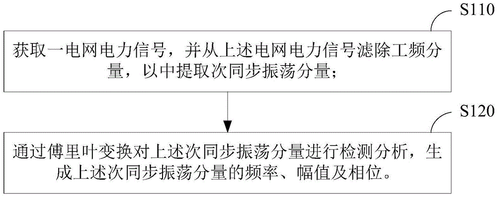
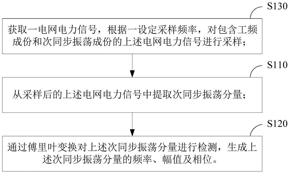
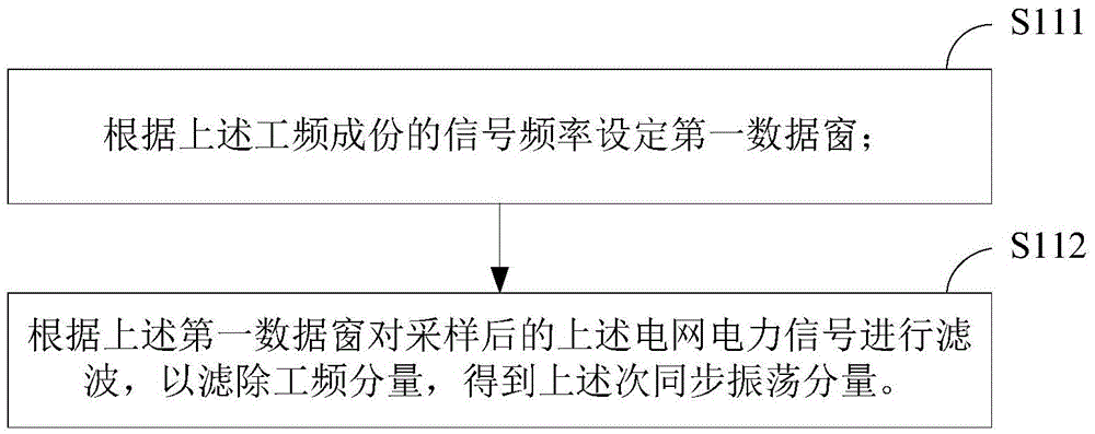
[0039] In order to make the objectives, technical solutions, and advantages of the embodiments of the present invention clearer, the following describes the embodiments of the present invention in further detail with reference to the accompanying drawings. Here, the exemplary embodiments of the present invention and the description thereof are used to explain the present invention, but not as a limitation to the present invention.

[0040] In the various embodiments of the present invention, "power system" may refer to power generation, power supply (including power transmission, transformation, and distribution), power-using facilities, and relay protection and safety automatic devices required to ensure the normal operation of these facilities , Metering devices, power communication facilities, automation facilities, etc. "Power frequency" can refer to the standard frequency of alternating current in the power industry, in my country it can refer to 50Hz. "Sub-synchronous osci...


PUM


Abstract

The invention provides on-line detection and filtering methods for a sub-synchronous oscillation part of a power system. The on-line detection method comprises: a power signal of a power grid is obtained and a power frequency component in the power signal of the power grid is filtered to extract a sub-synchronous oscillation component; and a detection analysis is carried out on sub-synchronous oscillation component by Fourier transform to generate a frequency, an amplitude, and a phase of the sub-synchronous oscillation component. According to the on-line detection and filtering methods provided by the embodiment of the invention, the sub-synchronous oscillation part in the power signal can be detected and filtered rapid and accurately.

Description

Technical field [0001] The invention relates to the field of electric power, in particular to an online detection and filtering method of subsynchronous oscillation components of a power system. Background technique [0002] In the prior art, the monitoring method of the sub-synchronous oscillation is mainly aimed at the sub-synchronous resonance (Sub-Synchronous Resonance, SSR) caused by series compensation. Monitoring can only be carried out on-site in the power plant. The monitoring signals are mainly taken from the generator set. The monitoring methods can be divided into two measurement methods: mechanical measurement and electrical measurement according to the difference of measurement signals. [0003] The subsynchronous oscillation monitoring method based on the measurement of mechanical quantities uses the dynamic process of the rotor movement of the generator set under the excitation of environmental disturbance to identify the subsynchronous oscillation mode. The large ...

Claims


Application Information

Patent Timeline
IPC IPC(8): G01R23/163H02J3/01
CPCG01R23/163H02J3/01Y02E40/40
Inventor 王茂海齐霞牛四清
Owner STATE GRID CORP OF CHINA
Why Eureka
Try Eureka