
Workpiece carrying bench on catenary

A workbench and catenary technology, which is applied to conveyor objects, transportation and packaging, conveyor control devices, etc., can solve the problems of positioning accuracy differences, high precision, waste, etc., and achieve reduced manufacturing costs and fast response speed , to achieve a simple effect

Active Publication Date: 2016-05-25
UNIV OF JINAN +1
View PDF5 Cites 1 Cited by
  • Summary
  • Abstract
  • Description
  • Claims
  • Application Information

AI Technical Summary

Problems solved by technology

[0003] However, due to the different actual working conditions, in terms of workpiece positioning accuracy, some have relatively high requirements for workpiece positioning accuracy, while others have relatively low requirements. Different workpieces have different positioning accuracy, and even have relatively large differences. , for some workpieces placed on the turntable of the worktable, the angle error of 5 degrees or even 10 degrees will not affect its handling
[0004] Therefore, in some applications, it is not necessary to use a catenary workpiece handling table with too high positioning accuracy. To some extent, too high accuracy is also a waste
In view of this, for example, the above-mentioned patent document CN102633114A adopts a servo motor to obtain relatively high control accuracy, relatively speaking, its cost is relatively high, and the use of forward and reverse control requires frequent start and stop of the servo motor, which is likely to cause the servo motor overheat
[0005] For forward and reverse control, for example, the reducer used for rotation is usually a gearbox, and there is a gap between the gears, and the conversion of forward and reverse will produce errors.
[0006] In addition, in view of the fact that the above-mentioned patent document CN102633114A adopts visual recognition, or a workpiece positioning method based on image processing, relatively speaking, the cycle from image shooting to recognition calculation is relatively long, and the efficiency is relatively low

Method used

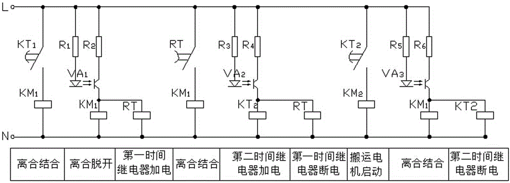
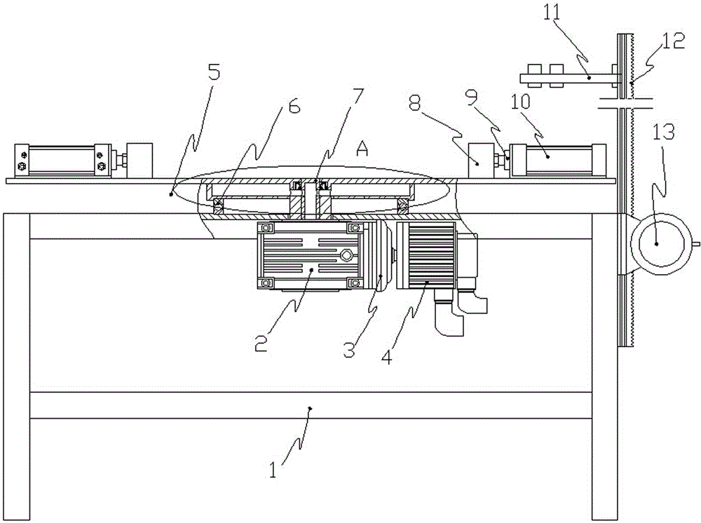

Image

  • Workpiece carrying bench on catenary
  • Workpiece carrying bench on catenary
  • Workpiece carrying bench on catenary

Examples


Embodiment Construction

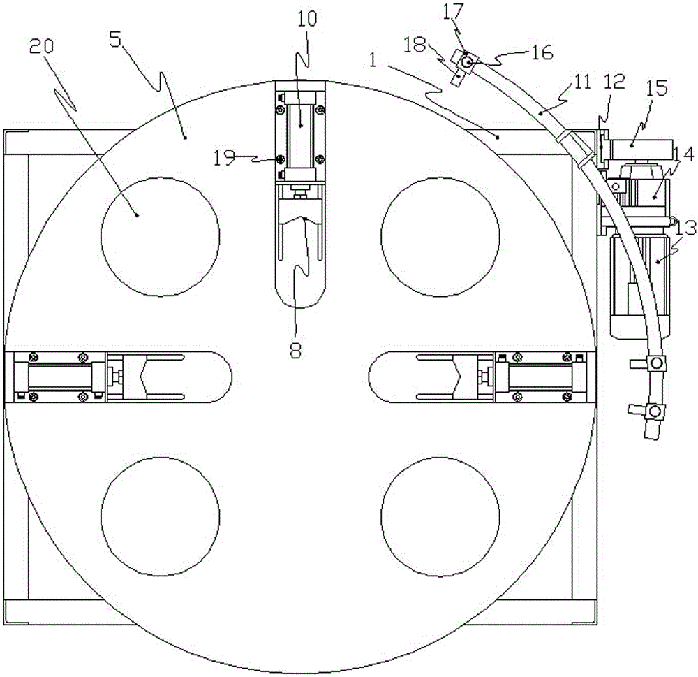
[0034] Regarding the reflective photoelectric sensor 18, also known as a reflective photoelectric switch, the common one is a reflective infrared photoelectric sensor, which is a small photoelectric component that can detect the change in the light intensity it receives. In the early stage, it is used to detect whether the object is sensed or not. It is composed of an infrared emitting tube and an infrared receiving tube. Its emission wavelength is 780nm-1mm. The transmitter has a calibration lens to focus the light. Receiver, the receiver cable connects this set to a vacuum tube amplifier.

[0035] The detection object is the transmitter and detector between the slotted switch and the block light path when it enters the gap. When the object approaches the arc extinguishing chamber, a part of the light collected by the receiver is reflected from the object to the photoelectric element. It uses the object to shield or reflect the infrared beam, and is gated by the synchronization ...


PUM


Abstract

The invention discloses a workpiece carrying bench on a catenary, comprising: a work rack; a turnplate mounted on the work rack through a rotary support; a fixture mounted on the turnplate and used to concentrically position and clamp the workpiece with the turnplate; a drive device that drives the turnplate to adjust its rotational angle; a first reflecting photoelectric sensor; a second reflecting photoelectric sensor; a third reflecting photoelectric sensor. The carrying bench according to the invention is relatively low in manufacture cost and has high positioning precision.

Description

Technical field [0001] The invention relates to a work platform for handling workpieces on catenary lines. Background technique [0002] The catenary workpiece handling table disclosed in Chinese Patent Document CN102633114A is the first catenary workpiece handling table proposed by the applicant, which can solve the problem of the conveyed workpiece or the angle placed on the table. Undesirable problem, so that the handling equipment can accurately hang the workpiece on the catenary production line. [0003] However, because the actual working conditions are not the same, as far as the positioning accuracy of the workpiece is concerned, some have higher requirements for the positioning accuracy of the workpiece, and some have lower requirements. Different workpieces have different positioning accuracy, or even larger differences. For some workpieces placed on the turntable of the worktable, the angle error of 5 degrees or even 10 degrees will not affect their handling. [0004] Th...

Claims


Application Information

Patent Timeline
Patent Type & Authority Applications(China)
IPC IPC(8): B65G47/61B65G29/00B65G43/00
CPCB65G29/00B65G43/00B65G47/61B65G2201/02B65G2203/0283B65G2203/044
Inventor 张如剑李长春张宏高李映君陈乃建
Owner UNIV OF JINAN
Learn More