
Corn straw crushing device

A crushing device and technology of corn stalks, which are applied in the direction of balers, cutters, agricultural machinery and implements, etc., can solve the problems of size reduction, incapable of corn stalk bundling and coating operations, etc., and achieve convenient and fast crushing Effect

Inactive Publication Date: 2016-05-25
NANJING AGRI MECHANIZATION INST MIN OF AGRI +1
View PDF3 Cites 9 Cited by
  • Summary
  • Abstract
  • Description
  • Claims
  • Application Information

AI Technical Summary

Problems solved by technology

[0008] The present invention adopts the above-mentioned technical scheme, thereby bringing the following effects: the stalk is cut along its moving direction (longitudinal direction) by the longitudinal cutter, so that the size of the stalk on the section is reduced; the stalk after slitting is moved The interactive rubbing board and the fixed rubbing board rub the straw so that the size of the straw in the section is reduced again. Finally, the straw that has been rubbed into filaments is cut into a controllable length along the transverse direction by a horizontal cutter. It is convenient and fast to crush corn stalks to specific specifications, which is beneficial to the subsequent bundling and comprehensive utilization of straw, and completely solves the problem of using separation operations. The size of corn stalk crushing and the size required for straw baling are very different from each other, which cannot be done well. The difficulty of bundling and coating the corn stalks, so that the subsequent bundling and coating can be carried out properly

Method used


Image

  • Corn straw crushing device
  • Corn straw crushing device
  • Corn straw crushing device

Examples


Embodiment

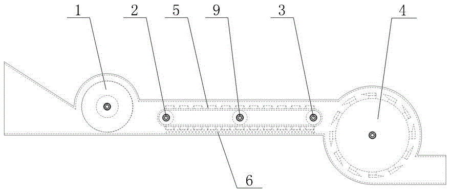
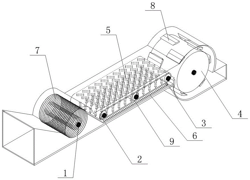
[0023] The corn stalk pulverizing device of present embodiment, as figure 1 and figure 2 As shown, it includes a housing, which is provided with a first rotating shaft 1, a driving shaft 2, a driven shaft 3, a second rotating shaft 4 arranged relatively parallel to each other, and a mobile rubbing plate 5 and a fixed rubbing plate arranged up and down relative to each other. board6.

[0024] The first rotating shaft 1 is located at the entrance of the crushing device, the second rotating shaft 4 is located at the exit of the crushing device, and the driving shaft 2 and the driven shaft 3 are located between the first rotating shaft 1 and the second rotating shaft 4 .

[0025] A longitudinal cutter 7 perpendicular to its centerline is fixed on the circumference of the first rotating shaft 1 , and a transverse cutter 8 parallel to its centerline is fixed on the circumference of the second rotation shaft 4 .

[0026] The mobile rubbing board 5 is a conveyor-belt-shaped rubbing...


PUM


Abstract

The invention relates to a corn straw crushing device and belongs to the technical field of crop processors for agricultural harvesting. The crushing device comprises a shell, wherein the shell is internally provided with a first rotary shaft, a driving shaft, a driven shaft, a second rotary shaft, a movable rubbing plate and a fixed rubbing plate; the first rotary shaft, the driving shaft, the driven shaft and the second rotary shaft are arranged in a manner of being parallel to each other; the movable rubbing plate and the fixed rubbing plate are arranged relatively up and down; the first rotary shaft and the second rotary shaft are located at the inlet and the outlet of the crushing device respectively; the driving shaft and the driven shaft are located between the first rotary shaft and the second rotary shaft; a longitudinal cutter is fixedly arranged on the first rotary shaft and a transverse cutter is fixedly arranged on the second rotary shaft; the movable rubbing plate is a conveyor-belt-shaped rubbing plate formed by mutually connecting plate-shaped rubbing plates; the front and rear ends of the movable rubbing plate sleeve the driving shaft and the driven shaft respectively; a straw rubbing channel is formed between the movable rubbing plate and the fixed rubbing plate. With the adoption of the crushing device, corn straws can be conveniently and rapidly crushed to specific sizes so that subsequent bundling and film packaging work can be conveniently carried out.

Description

technical field [0001] The invention relates to a corn stalk crushing device, which belongs to the technical field of crop processing machines for agricultural harvesting. Background technique [0002] Corn is one of the most important food crops in my country, with an annual output of more than 200 million tons. During corn harvesting operations, a large amount of corn stover is produced. [0003] The treatment methods of corn stalks mainly include direct incineration, straw returning to the field and straw recycling. However, the direct burning of straw not only pollutes the environment, but also causes waste of resources, and there are many safety hazards; using straw to return to the field on the spot consumes a lot of power, and the operating cost is high, which is prone to land nutritional imbalance, soil-borne diseases and insect pests, and slow straw maturity More importantly, it may lead to difficulties in planting the next crop in non-single-season planting areas...

Claims


Application Information

Patent Timeline
IPC IPC(8): A01D37/00A01D43/08
CPCA01D37/00A01D43/086
Inventor 朱德文谢虎张华王冬冬周进郑继立赵维松王鹏军李瑞容曹杰韩柏和曲浩丽陈永生
Owner NANJING AGRI MECHANIZATION INST MIN OF AGRI
Learn More