clutch device

A clutch device and friction clutch technology, applied in transmission, transmission control, fluid transmission, etc., can solve problems such as poor efficiency, poor starting process, and troublesome emergency response, so as to improve efficiency and reduce losses. energy effect

Active Publication Date: 2019-06-14
SCHAEFFLER TECH AG & CO KG
View PDF6 Cites 0 Cited by
  • Summary
  • Abstract
  • Description
  • Claims
  • Application Information

AI Technical Summary

Problems solved by technology

[0006] However, the mentioned solutions also have disadvantages
The first solution path usually has less good efficiency
The second solution approach usually implements the start-up process worse than the first solution approach
Here, too, emergency response can only be implemented with great effort

Method used


Image

  • clutch device
  • clutch device
  • clutch device

Examples


Embodiment Construction

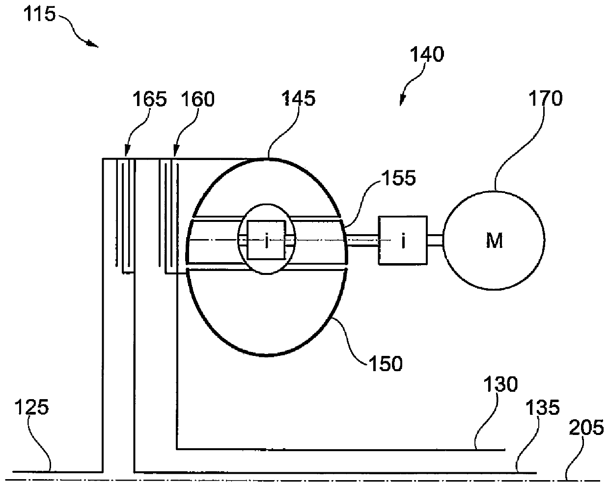
[0025] figure 1 A drive train 100 is shown, in particular for operation on a motor vehicle. The drive train 100 is configured to be mounted between a drive motor 105 and drive wheels 110 (both not shown). The drive train 100 here includes a clutch device 115 and a transmission 120 . The clutch device 115 includes an input side 125 and a first output side 130 and a second output side 135 , each for connection to an associated input shaft of the transmission 120 . The transmission 120 is preferably a double-shift transmission which is provided for engaging or disengaging different gears between the respective output sides 130 , 135 of the clutch device 115 and the shaft leading to the drive wheels 110 . A torque converter 140 is arranged between the input side 125 and the first output side 130 . Torque converter 140 includes an impeller 145 , a turbine 150 , and an stator 155 disposed generally between impeller 145 and turbine 150 . The stator 155 changes the flow of fluid b...


PUM


Abstract

The invention discloses a clutch device used for a transmission system of a vehicle. The clutch device comprises an input side connected with a driving motor; a first output side and a second output side, which are respectively used for connection with an input shaft of a transmission. The clutch device comprises a torque converter connected between the input side and the first output side. The coupling of the torque converter is adjusted, and then the improving of the positive or negative rotating speed of the input side with respect to the first output side can be adjusted.

Description

technical field [0001] The invention relates to a clutch device, in particular for use in a drive train of a motor vehicle. More precisely, the invention relates to a clutch arrangement on a dual clutch transmission. Background technique [0002] The drive train on a motor vehicle includes the drive motor, clutch, transmission and drive wheels. The transmission is a shift transmission in which different gears can be engaged. In order to carry out a start-up or a gear change in a transmission as quickly, smoothly and without interruption of tractive force as possible, various clutch and transmission designs are known. [0003] A first solution provides that the hydraulic torque converter is connected to a serial planetary gear transmission. The starting process of the motor vehicle can be carried out particularly easily via the torque converter. Furthermore, due to the torque converter, no variable force lock-up occurs, which is known as “bounce” in friction disc clutches...

Claims


Application Information

Patent Timeline
Patent Type & Authority Patents(China)
IPC IPC(8): F16H61/14
CPCF16H61/56F16H41/26F16H45/02F16H61/688
Inventor M·贝尔M·格雷特尔D·赫尔科默L·G·麦克米利安
Owner SCHAEFFLER TECH AG & CO KG
Why Eureka
Try Eureka