Impeller of centrifugal fan

A centrifugal fan and impeller technology, applied in the mechanical field, can solve the problem of low connection stability and achieve the effect of simple processing

Inactive Publication Date: 2016-05-18
JIASHAN KAKU ELECTRICAL EQUIP
View PDF8 Cites 1 Cited by
  • Summary
  • Abstract
  • Description
  • Claims
  • Application Information

AI Technical Summary

Problems solved by technology

[0007] However, the above-mentioned impeller body and impeller cover plate are directly connected by fasteners, and because the blades on the impeller body are thin, the connection stability is not high

Method used


Image

  • Impeller of centrifugal fan
  • Impeller of centrifugal fan
  • Impeller of centrifugal fan

Examples


Embodiment 1

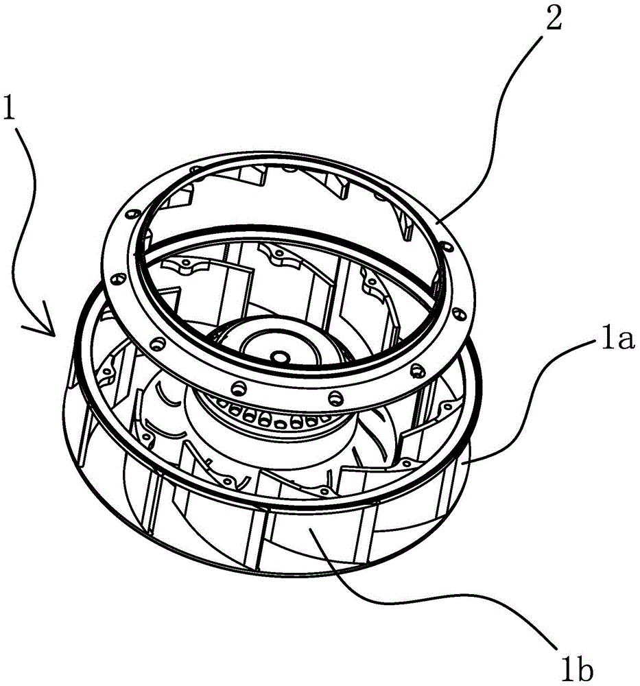
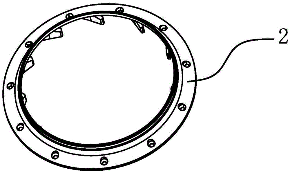
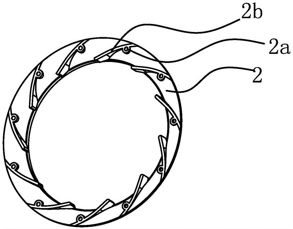
[0045] Such as figure 1 with figure 2 with image 3 with Figure 4 As shown, the impeller of the centrifugal fan includes an impeller body 1 and an end cover 2. The impeller body 1 includes a connecting seat 1a and several blades 1b. The above-mentioned blades 1b and the connecting seat 1a are of an integrated structure. The end cover 2 is a split structure, the inner edge of the above-mentioned blade 1b is connected with the connection seat 1a, the outer edge of the blade 1b has a connecting part 1, and the end cover 2 is circular and has a The first connecting part corresponds to the second connecting part, and the first connecting part and the second connecting part are connected by fasteners.

[0046] The number of the connecting part 1 and the connecting part 2 are the same, and the positions correspond to each other.

[0047] The first connecting part is a connecting block 1b1 protruding from the outer edge of the blade, and the connecting block 1b1 has a threaded h...

Embodiment 2

[0059] The structure of this embodiment is basically the same as that of the first embodiment, except that the impeller body and the end cover are made of magnesium alloy.


PUM


Abstract

The invention provides an impeller of a centrifugal fan, and belongs to the technical field of machinery, and the impeller solves the problem of high manufacturing difficulty in the prior art. The impeller of the centrifugal fan comprises an impeller body and an end cover, wherein the impeller body comprises a connecting base and a plurality of blades; the blades and the connecting base are of an integrated structure; the impeller body and the end cover are of an split type structure; the inner side edges of the blades are connected to the connecting base; the outer side edges of the bases are provided with a connecting part I; the end cover is in the shape of a circular ring, and is provided with a connecting part II which corresponds to the connecting part I; and the connecting part I and the connecting part II are connected through a fastener. The impeller of the centrifugal fan provided by the invention is compact in structure and is relatively low in processing difficulty.

Description

technical field [0001] The invention belongs to the technical field of machinery and relates to an impeller, in particular to an impeller in a centrifugal fan. Background technique [0002] The centrifugal fan is a machine that relies on the input mechanical energy to increase the gas pressure and discharge the gas. It is a driven fluid machine. Centrifugal fans are widely used in ventilation, dust removal and cooling of factories, mines, tunnels, cooling towers, vehicles, ships and buildings; ventilation and induction of boilers and industrial furnaces; cooling and cooling of air conditioning equipment and household appliances Ventilation; drying and selection of grain; wind tunnel wind source and inflation and propulsion of hovercraft, etc. [0003] The centrifugal fan is based on the principle of converting kinetic energy into potential energy. It uses a high-speed rotating impeller to accelerate the gas, then decelerates, changes the flow direction, and converts kinetic...

Claims


Application Information

Patent Timeline
IPC IPC(8): F04D29/28
CPCF04D29/281
Inventor 郭建议
Owner JIASHAN KAKU ELECTRICAL EQUIP
Why Eureka
Try Eureka