Eureka AIR delivers breakthrough ideas for toughest innovation challenges, trusted by R&D personnel around the world.

Multi-functional bending device

A bending device and a multi-functional technology, applied in the field of multi-functional bending devices, can solve the problems that it is difficult to accurately locate the size of the bending edge, difficult to ensure the flatness of the workpiece, and the level of skilled workers, and reduce the skill requirements of employees. , Eliminate the leveling process, the effect of high product accuracy

Inactive Publication Date: 2016-05-18
SHANGHAI TRIOWIN INTELLIGENT MACHINERY CO LTD
View PDF5 Cites 10 Cited by
  • Summary
  • Abstract
  • Description
  • Claims
  • Application Information

AI Technical Summary

Problems solved by technology

At present, there are only two movable baffles behind the bending of sheet metal parts, which can be adjusted to move forward, backward, left, and right to ensure the size of the bending edge. However, the previous process of bending parts adopts shearing plate or CNC plasma blanking, and these processes will cause deformation of the workpiece. , even after correction, it is difficult to ensure the flatness requirements of the workpiece, and it is difficult to accurately locate the bending edge size after the workpiece is deformed
[0003] At the same time, because the stopper is parallel to the groove of the bending machine, the bending end edge of the workpiece needs to be parallel to the bending groove when bending the sheet metal part. When the bending end edge forms an angle with the stopper, it cannot be bent directly. Only the workpiece can be marked and bent, but the level of skilled workers is high, and the bender must accurately calculate the position of the bending line before marking the line

Method used


Image

  • Multi-functional bending device
  • Multi-functional bending device

Examples


Embodiment Construction

[0022] The present invention will be described in detail below in conjunction with the accompanying drawings and specific embodiments. This embodiment is carried out on the premise of the technical solution of the present invention, and detailed implementation and specific operation process are given, but the protection scope of the present invention is not limited to the following embodiments.

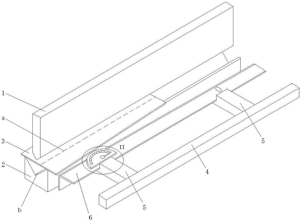
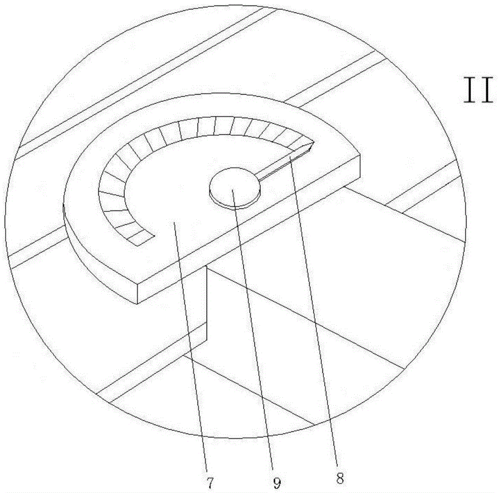
[0023] Such as figure 1 As shown, a multifunctional bending device includes a bending machine blade 1 and a bending machine lower die 2, a workpiece 3 is placed between the bending machine blade 1 and the bending machine lower die 2, and also includes a bending stop plate mechanism and angle measuring instrument, the bending baffle mechanism includes a baffle crossbeam 4, two stop blocks 5 and a bending baffle 6, the bending baffle 6 is respectively connected to the two stop blocks 5 through nuts and bolts 9, It is located on one side of the lower die 2 of the bending machine and is ...


PUM


Abstract

The invention relates to a multi-functional bending device. The multi-functional bending device comprises a bender cutting board and a bender lower die, wherein a workpiece is placed between the bender cutting board and the bender lower die. The multi-functional bending device further comprises a bending baffle mechanism and an angle measurement instrument, wherein the bending baffle mechanism comprises a baffle beam, two stop dogs and a bending baffle; the bending baffle is separately connected with the two stop dogs, is arranged on one side of the bender lower die and is close to the workpiece; the two stop dogs are separately connected with the baffle beam; and the angle measurement instrument is arranged on the bending baffle. According to the angular value of the angle measurement instrument, the value of an angle between the edge of the bending baffle and the lower die bending line of the bender lower die is regulated, the bending baffle is fixed, the workpiece is close to the bending baffle, and the bender cutting board carries out bending action. Compared with the prior art, the multi-functional bending device has the advantages of being high in universality, high in product precision, simple to operate and the like.

Description

technical field [0001] The invention relates to the field of mechanical equipment, in particular to a multifunctional bending device. Background technique [0002] The bending device is a mechanical device commonly used for processing profiles, and generally bends the processed profiles. At present, there are only two movable baffles behind the bending of sheet metal parts, which can be adjusted to move forward, backward, left, and right to ensure the size of the bending edge. However, the previous process of bending parts uses shearing or CNC plasma blanking, and these processes will cause deformation of the workpiece. , even after correction, it is difficult to ensure the flatness requirements of the workpiece, and it is difficult to accurately locate the bending edge size after the workpiece is deformed. [0003] At the same time, because the stopper is parallel to the groove of the bending machine, the bending end edge of the workpiece needs to be parallel to the bendin...

Claims


Application Information

Patent Timeline
Patent Type & Authority Applications(China)
IPC IPC(8): B21D5/14B21D43/00B21C51/00
Inventor 高斌胜李国振李文艺刘锐
Owner SHANGHAI TRIOWIN INTELLIGENT MACHINERY CO LTD
Why Eureka
Eureka Blog
Learn More