
A gas-liquid distribution plate for an upflow reactor

A gas-liquid distribution and reactor technology, applied in chemical instruments and methods, treatment with moving solid particles, chemical/physical processes, etc., can solve problems such as reducing the service life and operation cycle of catalysts, damaging catalyst performance, and affecting catalyst effects , to achieve the effect of improving internal utilization, increasing processing capacity, and saving reactor space

Active Publication Date: 2018-03-16
SINOPEC DALIAN RES INST OF PETROLEUM & PETROCHEMICALS CO LTD +1
View PDF11 Cites 0 Cited by
  • Summary
  • Abstract
  • Description
  • Claims
  • Application Information

AI Technical Summary

Problems solved by technology

Uneven material distribution will lead to temperature differences on the radial section, especially after the reactor size is enlarged, and even local overheating will occur, which will damage the performance of the catalyst, thereby greatly reducing the service life and operation cycle of the catalyst
In addition, due to the small amount of impurities in the raw materials and the rust and dirt entrained by impacting the pipes and equipment when they flow through the system, if they accumulate on the surface of the catalyst bed, they will quickly block the circulation channels, resulting in uneven distribution of raw materials and greatly affecting Catalyst effect even increases reactor pressure drop

Method used


Image

  • A gas-liquid distribution plate for an upflow reactor
  • A gas-liquid distribution plate for an upflow reactor
  • A gas-liquid distribution plate for an upflow reactor

Examples


Embodiment 1

[0040] Using the gas-liquid distribution plate of the present invention to carry out the hydrogenation reaction of fluidized bed residual oil, the reaction conditions are: reaction temperature 396°C, reaction pressure 15MPa, hydrogen-oil ratio 500:1, volume space velocity 0.4h -1 . The properties of the residual oil are shown in Table 1, and the evaluation results are shown in Table 2. The reactor is filled with FZC-24 produced by Fushun Petrochemical Research Institute.

Embodiment 2

[0042] Using the gas-liquid distribution plate of the present invention to carry out the hydrogenation reaction of fluidized bed residue, the reaction conditions are: reaction temperature 396 ° C, reaction pressure 15 MPa, hydrogen-oil ratio 500:1, volume space velocity 0.4 h -1 . The properties of the residual oil are shown in Table 1, and the evaluation results are shown in Table 2. The reactor is filled with FZC-24 produced by Fushun Petrochemical Research Institute. At the same time, the gas-liquid distributor of the present invention (constituted as FZC-11) is also installed in the inlet pipeline at the bottom of the reactor.

Embodiment 3

[0044] The gas-liquid distributor of the present invention is used to carry out double fluidized bed reactors connected in series to carry out hydrogenation reaction of residual oil. The reaction conditions are: reaction temperature 396°C / 396°C, reaction pressure 15MPa, hydrogen-oil ratio 500:1, total volume space velocity 0.2 h -1 . The properties of the residual oil are shown in Table 1, and the evaluation results are shown in Table 2. FZC-24 and FZC-34 produced by Fushun Petrochemical Research Institute are respectively filled inside the first and second reverse.


PUM

PropertyMeasurementUnit
heightaaaaaaaaaa
heightaaaaaaaaaa
diameteraaaaaaaaaa

Abstract

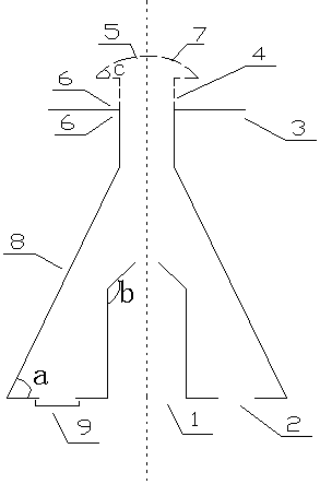
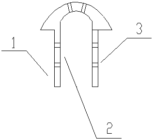
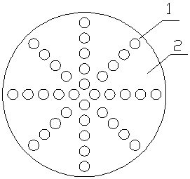
The invention discloses a gas-liquid distribution plate for an upflow reactor, comprising a plate, a plurality of distribution holes are uniformly distributed on the plate, and a gas-liquid distributor is installed on each distribution hole, wherein the The gas-liquid distributor includes a catalytic material net and a support. The catalytic material net is above the plate, and the support is below the plate. The bottom of the catalytic material net and the top of the support are respectively fixed in the distribution holes of the plate by bolts. The catalytic material net The bottom communicates with the top of the support body, wherein the catalytic material network is made of catalytically active material in hydrogenation reaction. The gas-liquid distribution plate is simple in structure, easy to operate, large in operation flexibility and good in distribution effect, and can meet the needs of reactor flow distribution and long-term stable operation.

Description

technical field [0001] The invention relates to a gas-liquid distribution plate for an upflow reactor, in particular to a gas-liquid distribution plate for a fluidized bed reactor in which gas and liquid flow upward. Background technique [0002] In reactors in petrochemical, fine chemical and other fields, gas-liquid distributors are widely used as important internal components. The gas-liquid distributor makes the material evenly distributed in the reactor, and the reactant is in good contact with the catalyst, which is an important factor for giving full play to the performance of the catalyst and the stable operation of the device. Uneven material distribution will lead to temperature differences on the radial section, especially after the size of the reactor is enlarged, and even local overheating will occur, which will damage the performance of the catalyst, thereby greatly reducing the service life and operation cycle of the catalyst. In addition, due to the small am...

Claims


Application Information

Patent Timeline
Patent Type & Authority Patents(China)
IPC IPC(8): B01J8/24C10G49/16
Inventor 刘建锟卜岩朱峰杨涛方向晨蒋立敬
Owner SINOPEC DALIAN RES INST OF PETROLEUM & PETROCHEMICALS CO LTD
Learn More