Transmission line driving circuit used for automatic correction of impedance matching

A drive circuit and impedance matching technology, applied in the field of transmission line drive circuits that can automatically correct impedance matching, can solve problems such as lack of power transmission, electromagnetic interference, circuit damage, etc., and achieve a wide range of applications.

Active Publication Date: 2016-05-11
REALTEK SEMICON CORP
View PDF4 Cites 1 Cited by
  • Summary
  • Abstract
  • Description
  • Claims
  • Application Information

AI Technical Summary

Problems solved by technology

Conversely, when the impedances of the output circuit and the input circuit do not match, not only will the maximum power transmission not be obtained, but the circuit may also be damaged.
[0003] For example, when the impedance of the output circuit and the input circuit do not match, the differential output current of the output circuit will be asymmetrical, which will lead to the problem of electromagnetic interference (EMI)
In addition, when the impedance of the output circuit and the input circuit do not match, the return loss (ReturnLoss) of the system will also increase

Method used


Image

  • Transmission line driving circuit used for automatic correction of impedance matching

Examples


Embodiment Construction

[0010] Embodiments of the present invention will be described below in conjunction with related drawings. In the drawings, the same reference numerals represent the same or similar elements or method flows.

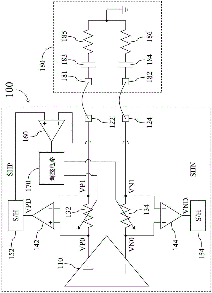
[0011] figure 1 It is a simplified functional block diagram of a transmission line driver circuit (transmission line driver circuit) 100 according to an embodiment of the present invention. Such as figure 1 As shown, the transmission line driving circuit 100 includes a transmission line driving amplifier (transmission line driving amplifier) ​​110, a first signal node (signal node) 122, a second signal node 124, a first adjustable resistor 132, a second adjustable resistor 134, a first voltage difference A signal difference generating circuit 142 , a second voltage difference generating circuit 144 , a first sample and hold circuit 152 , a second sample and hold circuit 154 , a comparison circuit 160 and an adjustment circuit 170 .

[0012] The transmission line drivin...


PUM


Abstract

The invention provides a transmission line driving circuit used for automatic correction of impedance matching. The transmission line driving circuit comprises a transmission line driving amplifier provided with a first transmission end and a second transmission end; a first signal node; a second signal node; a first adjustable resistor disposed between the first transmission end and the first signal node; a second adjustable resistor disposed between the second transmission end and the second signal node; a first voltage difference generating circuit, which is coupled with two ends of the first adjustable resistor, and is used to generate a first voltage difference; a second voltage difference generating circuit, which is coupled with two ends of the second adjustable resistor, and is used to generate the second voltage difference; a first sampling and maintaining circuit, which is used to generate a first sampling signal according to the first voltage difference; a second sampling and maintaining circuit, which is used to generate a second sampling signal according to the second voltage difference; a comparison circuit, which is used to compare the first sampling signal and the second sampling signal; and an adjusting circuit, which is used to adjust at least one of the first adjustable resistor and the second adjustable resistor according to the comparison result of the comparison circuit.

Description

technical field [0001] The invention relates to a transmission line drive circuit, in particular to a transmission line drive circuit capable of automatically correcting impedance matching. Background technique [0002] In order to transmit signals and energy efficiently, ideally, the output circuit and the input circuit should work in an impedance matching state. That is, the internal resistance of the output circuit should be equal to the input impedance of the output circuit, and the output impedance of the output circuit should be equal to the impedance of the input circuit (generally also referred to as load). Maximum power transfer is achieved when the impedances of both the output and input circuits match each other. On the contrary, when the impedances of the output circuit and the input circuit do not match, not only the maximum power transmission cannot be obtained, but also the circuit may be damaged. [0003] For example, when the impedances of the output circu...

Claims


Application Information

Patent Timeline
Patent Type & Authority Applications(China)
IPC IPC(8): H03H11/28
Inventor 李朝政林见儒王士伟柯冠鸿
Owner REALTEK SEMICON CORP
Why Eureka
Try Eureka