
Capacitive touch panel

A touch panel and capacitive technology, applied in the direction of electrical digital data processing, instruments, data processing input/output process, etc., can solve the problems of many wires, serious wire signal interference, and inability to sense, so as to achieve uniform distribution of electric field, Avoid insensible, range-increasing effects

Inactive Publication Date: 2016-05-11
HYCON TECH
View PDF7 Cites 0 Cited by
  • Summary
  • Abstract
  • Description
  • Claims
  • Application Information

AI Technical Summary

Problems solved by technology

This patent also discloses the method of connecting the shielding induction unit with a wire to form a shielding induction group, which is connected to the control circuit through the wire, and the control circuit provides a signal to the conductive group or the shielding induction group through the wire, which has improved electric field Distribution and the effect of increasing the sensing sensitivity, but the disadvantage is the increase in the number of wires and the complexity of the control circuit
[0007] In U.S. Patent No. 6970160 and Taiwan Patent No. I347545, although they all disclose the function of sensing the user's touch on the touch panel, the conductive units in these existing patent technologies are all Inhomogeneous distribution of induced electric field and limitation of sensing area
Whether the shape of the conductive unit in the previous case is square, hexagonal or other shapes, the sensing area is only on the edge of the conductive unit. When the user only touches the center of the conductive unit, the conductive unit cannot sense, so the conductive unit The area must be smaller than the contact area of ​​the user's finger, otherwise there will be an area that cannot be sensed
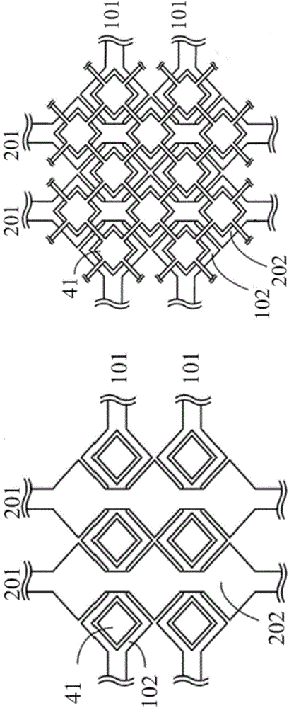
[0008] Taiwan Patent No. I430162 Invention Patent Case discloses the method of digging a hole in the center of the conductive unit, and hollowing out the center of the conductive unit and adding a shielding sensing area. Although the negative touch effect is improved, it can only be used in the conductive unit. edge sensing
This patent also discloses a method of providing signals to the shielding induction group. Although it has the effect of improving the electric field distribution and increasing the induction sensitivity, the disadvantage is that the number of wires and the complexity of the control circuit are increased, resulting in serious signal interference between the wires. If it is applied to a large-size touch panel, it will be difficult to realize due to too many wires

Method used


Image

  • Capacitive touch panel
  • Capacitive touch panel
  • Capacitive touch panel

Examples


Embodiment Construction

[0032] The present invention will be more specifically described with reference to the following examples. Please note that the following descriptions of the embodiments of the present invention are for illustrative purposes only; they are not meant to be exhaustive or limited to the disclosed form.

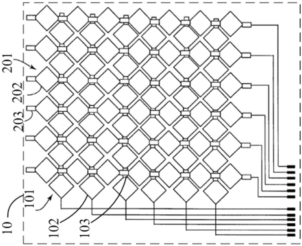
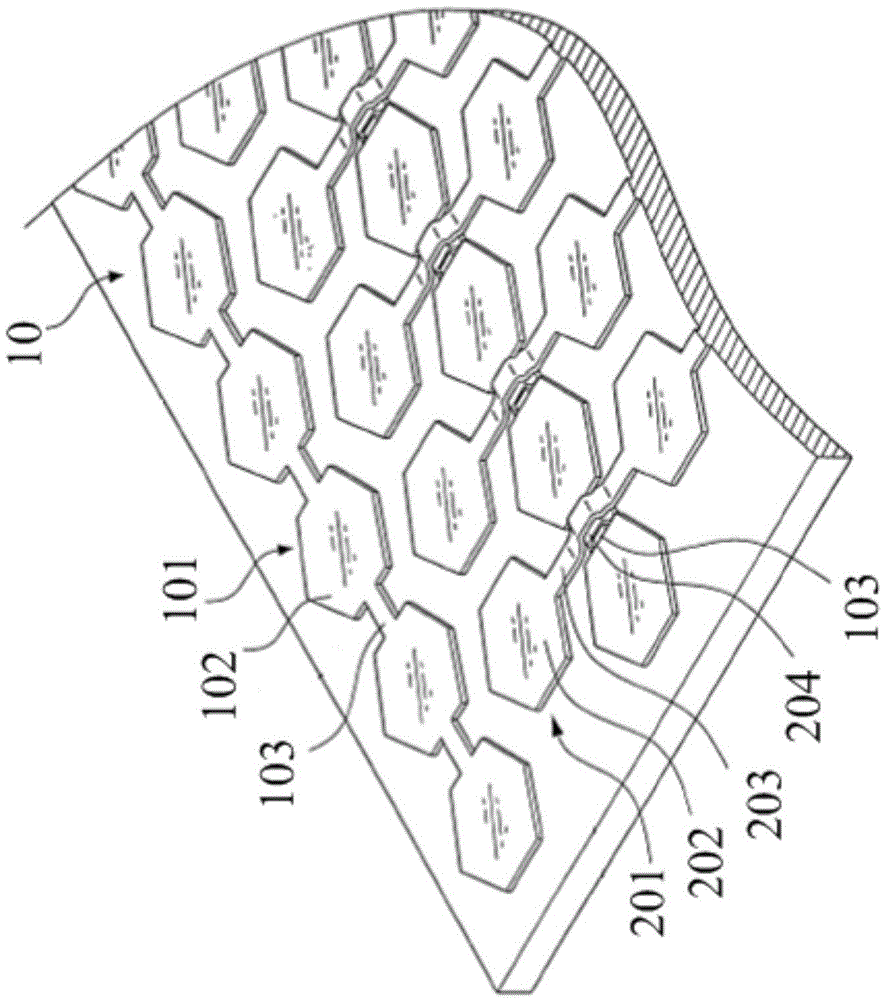
[0033] For a first embodiment of the invention see Figure 4 , which shows the structure of a single-layer inductive capacitive touch panel. The capacitive sensing layer includes 4 horizontal first-axis conductive groups, 5 vertical second-axis conductive groups, and 80 suspended sensing units. Each first axial conductive group includes six first axial conductive units, wherein adjacent first axial conductive units are directly connected by wires. And each second axial conductive group includes five second axial conductive units, wherein the adjacent second axial conductive units are covered with insulating material and then connected with wires on the surface of the insulating...


PUM


Abstract

The invention discloses a capacitive touch panel. The framework comprises two axial electric conduction groups, wherein each electric conduction group consists of a plurality of electric conduction units connected by a conductor; the electric conduction groups of different axial directions are isolated by insulation materials; the adjacent electric conduction units of different axial directions generate an electric field and induction capacitance when a control signal is provided; and a touch position is detected. The capacitive touch panel provided by the invention furthermore comprises a plurality of suspension induction units, wherein each suspension induction unit is distributed between the adjacent electric conduction units. The suspension induction units can generate new induction capacitance without being connected by the conductor or providedwith signals, and the capacitive touch panel has the advantages that induction fields are evenly distributed and a touch induction area is enlarged.

Description

technical field [0001] The invention relates to a touch panel, in particular to a capacitive touch panel. Touch panels (TouchPanel) have been widely used in home appliances, communications, electronic information and other products. For example, personal digital assistants (PDAs), various home appliances, game input interfaces, etc. are currently widely used in commercial use. Through the integration of the touchpad and the display, users can use their fingers or stylus to click and input the action they want to perform according to the function options on the display screen, and it can be used in public system query tools to provide convenient operations. system. Background technique [0002] In an existing touch panel, a sensing area is arranged on the surface of a substrate, and the sensing area is used to sense a signal of a human finger or a sensing pen, so as to achieve the purpose of touch. Most of the materials used in the sensing area are transparent conductive f...

Claims


Application Information

Patent Timeline
Patent Type & Authority Applications(China)
IPC IPC(8): G06F3/044
Inventor 王惠民王佑仁
Owner HYCON TECH
Learn More