A steering gear main control valve group

A technology of main control valves and steering gears, applied in mechanical equipment, rudder steering, servo motor components, etc., can solve the problems of difficult hydraulic control force, limited flow capacity, high precision requirements, etc., and achieve flow capacity adaptation Strong performance, solve the effect of large leakage of slide valve and high degree of modularization

Active Publication Date: 2017-10-24
SHANGHAI MARINE EQUIP RES INST
View PDF8 Cites 0 Cited by
  • Summary
  • Abstract
  • Description
  • Claims
  • Application Information

AI Technical Summary

Problems solved by technology

[0006] Existing technical solution a is widely used in domestic small and medium-sized hydraulic steering gears and Japan's Kawasaki early hydraulic steering gears. The balance valve is a mechanical servo slide valve that automatically adjusts the opening of the valve port, and has functions such as locking the rudder and anti-negative torque. , although the structure is very compact, but its structure type is complicated, the accuracy requirement is very high, the processing is difficult, the cost is high, and it is sensitive to oil pollution. In addition, the flow capacity of the valve is limited, and it is generally used when the flow rate is not greater than 180L / min. , the torque is not higher than 800kNm small and medium-sized hydraulic steering gear, not suitable for large flow, high torque steering gear system
[0007] Technical solution b has many applications in foreign steering gear, such as the hydraulic steering gear produced by HATLAPA in Germany. This solution controls the hydraulic control directional valve through the pilot-level electromagnetic directional valve, and is mainly used for small and medium sized steering gears. In the system, it is not suitable for a large flow closed system. In addition, due to the slide valve structure, its flow capacity is limited. When the system flow is large, problems such as volume increase and hydraulic control force are difficult to overcome.
[0008] Technical solution c is also widely used in foreign steering gears. Its structure is relatively simple, but when the load changes frequently, especially when there is negative torque, the pulsation of the main circuit oil will cause the hydraulic control check valve to open and close frequently, which is easy The system will generate greater hydraulic vibration and noise, especially in medium and large hydraulic steering gears, which will cause greater hydraulic shock, causing certain harm to the equipment

Method used


Image

  • A steering gear main control valve group
  • A steering gear main control valve group
  • A steering gear main control valve group

Examples


Embodiment Construction

[0042] The present invention is described in further detail now in conjunction with accompanying drawing.

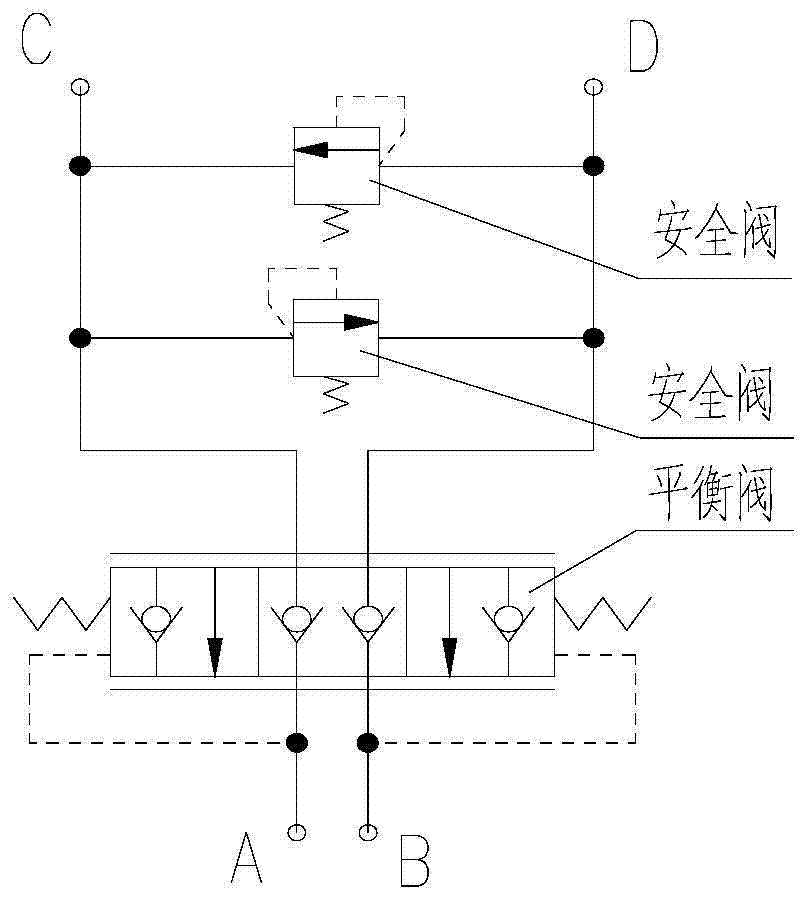
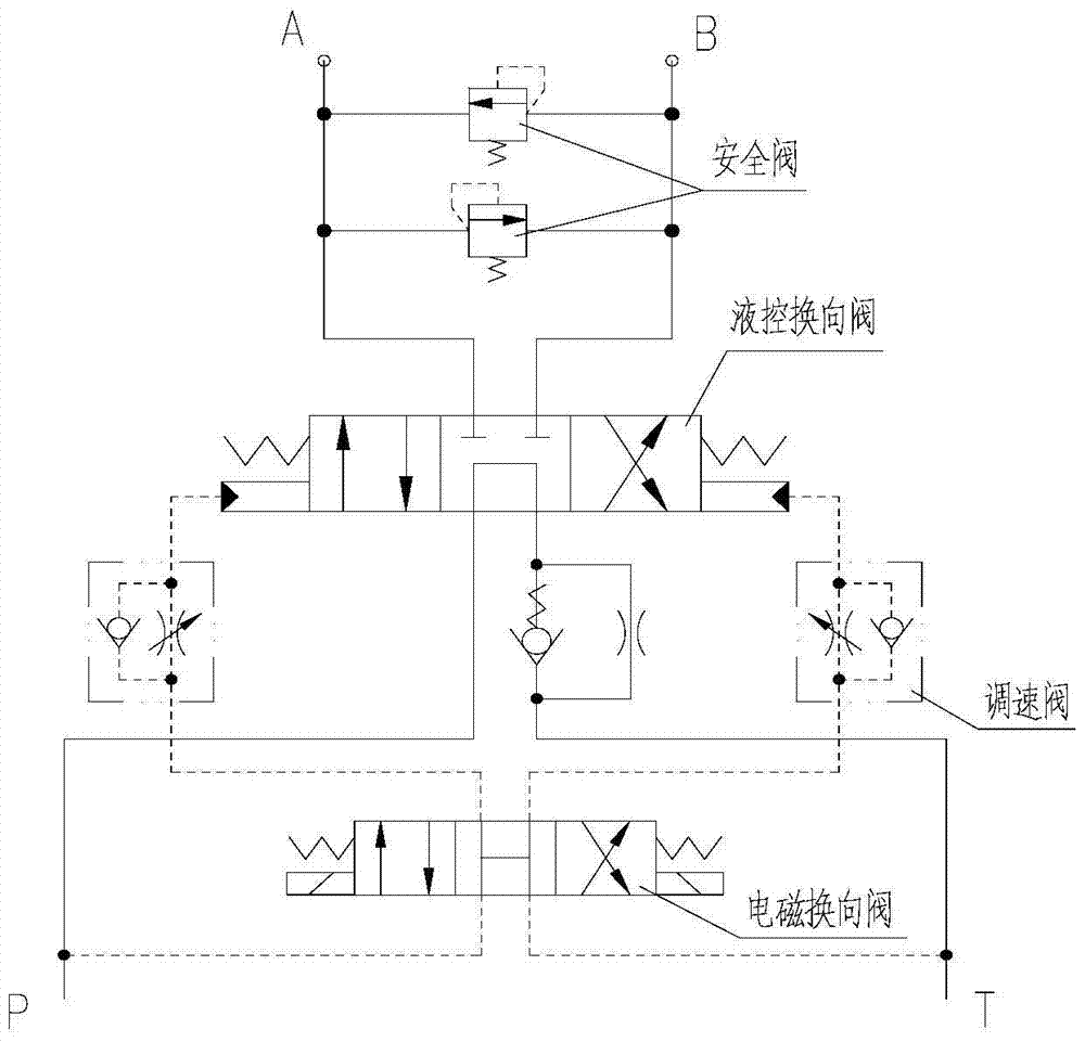
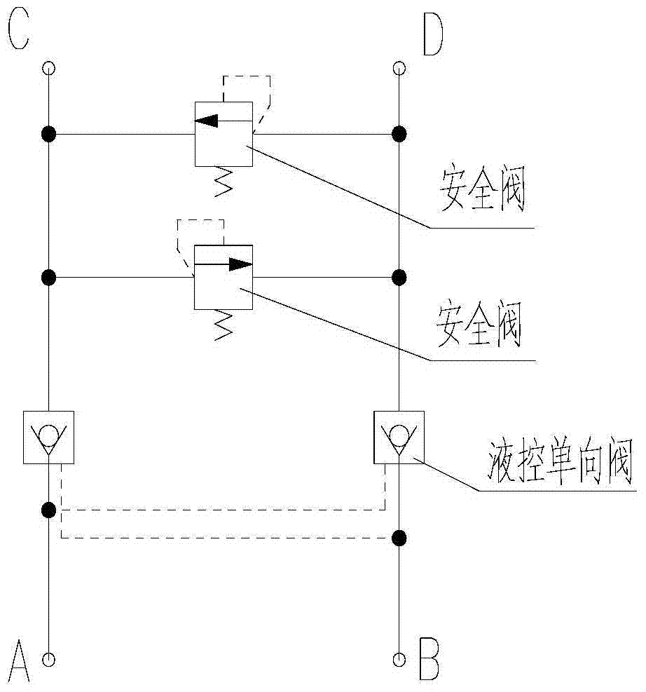
[0043] The structure of steering gear main control valve group of the present invention is as Figure 4a , Figure 4b , Figure 4c As shown, it includes: main valve body 1, electromagnetic reversing valve 2, second safety valve 3, third cartridge valve 4, check valve assembly 5, ball valve 6, flange 7, second cartridge valve 8, third A cartridge valve 9 and a first safety valve 10 .

[0044] The main valve body 1 is used for installing various hydraulic valve parts, and there are valve fitting passages and hydraulic oil circulation passages inside.

[0045] The second safety valve 3 and the first safety valve 10 adopt threaded plug-in type and are installed in the assembly hole on the main valve body 1, and are respectively connected in parallel with the A1 port circuit and B1 port circuit of the valve group for overpressure protection .

[0046] There are two flang...


PUM


Abstract

The invention provides a main control valve bank of a steering engine. A main valve body of the main control valve bank is provided with a connector A1 and a connector B1 which are connected with an oil pump. A ball valve is provided with a connector C1 and a connector D1 which are connected with the steering engine, wherein the connector A1 communicates with the connector C1, and the connector B1 communicates with the connector D1. When an electromagnetic reversing valve is not powered on, a third cartridge valve and a first cartridge valve are closed, and an access between an oil cylinder and the oil pump is cut off. A second cartridge valve controls an oil circuit to communicate with an oil drainage port G1 through the electromagnetic reversing valve, the second cartridge valve is opened, and the A1 communicates with the B1. When the electromagnetic reversing valve is powered on, pressure oil of a main circuit is divided into three ways through a one-way valve assembly and the electromagnetic reversing valve. By means of one way of the pressure oil, the access between the connector A1 and the connector B1 is cut off through the second cartridge valve, and the other two ways of the pressure oil push hydraulic one-way valves in cover plates of the third cartridge valve and the first cartridge valve to move correspondingly, so that the third cartridge valve and the first cartridge valve are in an open state. The connector A1 communicates with the connector C1, and the connector B1 communicates with the connector D1. The main control valve bank has the functions of non-loaded starting of a motor, steering engine locking and safety protection, and the main control valve bank has the characteristics that the function is rich, the integration level is high, and the standardization level is high.

Description

technical field [0001] The invention relates to the field of ships, in particular to a steering gear main control valve group. Background technique [0002] When the hydraulic steering gear is working, the main oil pump outputs pressure oil to the rudder steering mechanism according to the rudder direction, and pushes the executive parts such as the oil cylinder to drive the tiller to rotate to realize the rudder steering. Generally, a special valve group needs to be set up between the main oil pump and the rudder steering mechanism to perform functions such as oil control and pressure limiting protection. The valve group of the existing hydraulic steering gear is mainly realized by the following technical solutions: [0003] a. The balance safety valve group formed by the combination of the balance valve and the safety valve of the slide valve structure is realized (see figure 1 ); [0004] b. It is realized by using a valve group formed by a combination of a reversing v...

Claims


Application Information

Patent Timeline
Patent Type & Authority Patents(China)
IPC IPC(8): F15B13/02B63H25/30
CPCB63H25/30F15B13/02F15B2013/002F15B2013/004
Inventor 马瑜安姚庆涛邓攀何宇华夏海红
Owner SHANGHAI MARINE EQUIP RES INST
Why Eureka
Try Eureka