
An adjustable displacement spiral sand-carrying lifting device and process

A lifting device and screw technology, which is applied in the field of adjustable displacement screw sand-carrying lifting devices, can solve the problems of no mature technology, unreasonable oil well pump hanging depth, and unsatisfactory application effect, so as to improve the sinking degree , Improve lifting efficiency and reduce the effect of eccentric wear

Active Publication Date: 2017-12-05
CHINA PETROLEUM & CHEM CORP +1
View PDF6 Cites 0 Cited by
  • Summary
  • Abstract
  • Description
  • Claims
  • Application Information

AI Technical Summary

Problems solved by technology

[0002] In recent years, with the increase of complex well conditions in oilfields, the exploitation of complex wells has also become an important part of oilfield development. Issues such as horizontal lift of oil wells, sand-carrying lift, and thermal recovery of heavy oil have become difficult points in development. For horizontal lift, currently Ordinary oil pumps are often lowered into the vertical well section or the small-inclination well section, and the pumping is carried out above the horizontal section, which may easily cause the unreasonable depth of the oil well pump and reduce the liquid inlet efficiency
A small number of horizontal wells use electric pumps to lift, but due to the limitation of actual downhole working conditions and the influence of cable extrusion, the application effect is not ideal
The high-temperature sand-carrying lift in the horizontal section is currently in the exploratory stage, and no mature technology has been formed.

Method used


Image

  • An adjustable displacement spiral sand-carrying lifting device and process
  • An adjustable displacement spiral sand-carrying lifting device and process

Examples


Embodiment Construction

[0023] The detailed description and technical content of the present invention are described below with the accompanying drawings, but the accompanying drawings are only provided for reference and description, and are not intended to limit the present invention.

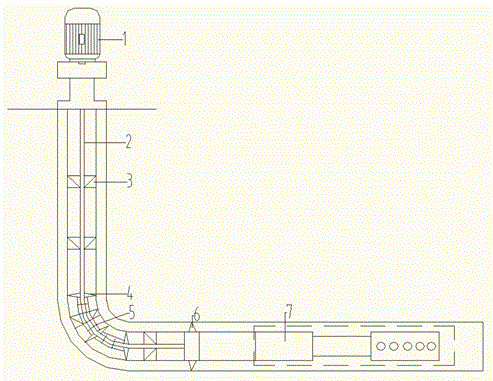
[0024] according to figure 1 and figure 2 As shown, an adjustable displacement screw sand-carrying lifting device includes a driving system 1, a sucker rod 2, and a double-stage spiral ladder lifting system 7 located in the horizontal section. The driving system sucker rod and the double The two-stage spiral ladder lifting system includes a large-displacement all-metal internal helical stator 701, a small-displacement all-metal internal helical stator 704, and a two-stage external helical rotor 702. The large-displacement The all-metal internal helical stator and the small-displacement all-metal internal helical stator are axially connected into one body through the intermediate relief pipe 703. The left half of th...


PUM


Abstract

The invention discloses an adjustable displacement screw sand-carrying lifting device and technology, wherein the device includes a driving system, a sucker rod, and a double-stage spiral ladder lifting system located in the horizontal section, and the driving system sucker rod It is connected with a two-stage spiral ladder lifting system, which includes a large-displacement all-metal internal helical stator, a small-displacement all-metal internal helical stator, and a two-stage external helical rotor. The metal internal helical stator and the small-displacement all-metal internal helical stator are axially connected into one body through the middle yield pipe. The left half of the two-stage external helical rotor is the large-displacement rotor end, and the right half is the small-displacement rotor. end. The invention utilizes the control system to control the surface drive system to perform rotational movement, and transmits the torque to the downhole double-stage spiral ladder lifting device through the sucker rod, and the lifting device lifts the production fluid in the oil layer to the ground through the oil pipe according to the displacement requirement. Realize high-efficiency sand-carrying lifting in the horizontal section under high temperature environment.

Description

technical field [0001] The invention relates to lifting equipment in a horizontal well, in particular to an adjustable displacement screw sand-carrying lifting device and technology. Background technique [0002] In recent years, with the increase of complex well conditions in oilfields year by year, the exploitation of complex wells has become an important part of oilfield development. Issues such as horizontal lift of oil wells, sand-carrying lift, and thermal recovery of heavy oil have become difficult points in development. For horizontal lift, currently Ordinary oil well pumps are often lowered into the vertical well section or the small-inclination well section, and the pumping is performed above the horizontal section, which may easily cause the unreasonable depth of the oil well pump and reduce the liquid inlet efficiency. A small number of horizontal wells are lifted by electric pumps, but due to the limitation of actual downhole working conditions and the influence...

Claims


Application Information

Patent Timeline
Patent Type & Authority Patents(China)
IPC IPC(8): E21B43/00E21B21/00
Inventor 王增林姜东郭海滨魏斌王东张雷张锡洲姜国良孟永闫文文费秀英戴超祁辛华
Owner CHINA PETROLEUM & CHEM CORP
Learn More