
Bypass valve while drilling

A bypass valve, while drilling technology, applied in the field of drilling, can solve the problems of troublesome operation, short service life, many wearing parts, etc., and achieve the effects of easy operation, reducing the number of trips and downhole accidents, and reducing downhole accidents.

Active Publication Date: 2018-11-09
CHINA PETROLEUM & CHEM CORP +1
View PDF7 Cites 1 Cited by
  • Summary
  • Abstract
  • Description
  • Claims
  • Application Information

AI Technical Summary

Problems solved by technology

[0007] The common disadvantage of the above existing drilling tool bypass valves is that they are all opened or closed by mechanical or hydraulic means, such as by throwing a ball or controlling the pump pressure.
The operation is relatively troublesome, and because there are many wearing parts, the number of times that can be switched is relatively small, and the service life is short

Method used


Image

  • Bypass valve while drilling
  • Bypass valve while drilling
  • Bypass valve while drilling

Examples


Embodiment Construction

[0027] The present invention will be further described below in conjunction with the accompanying drawings and specific embodiments.

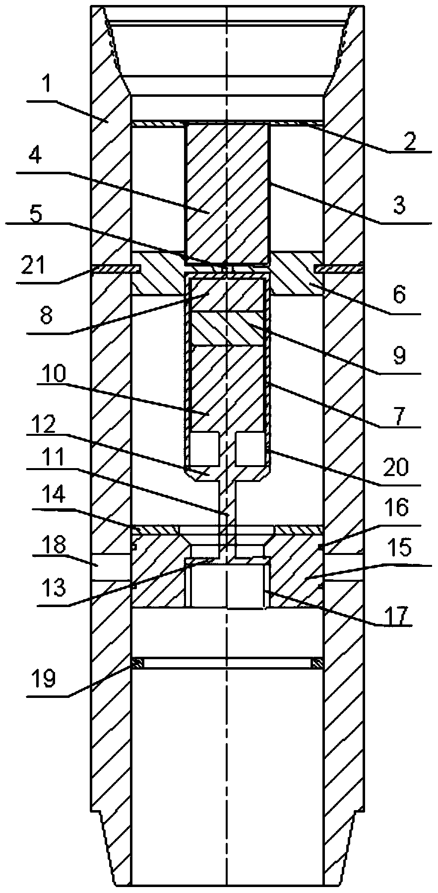
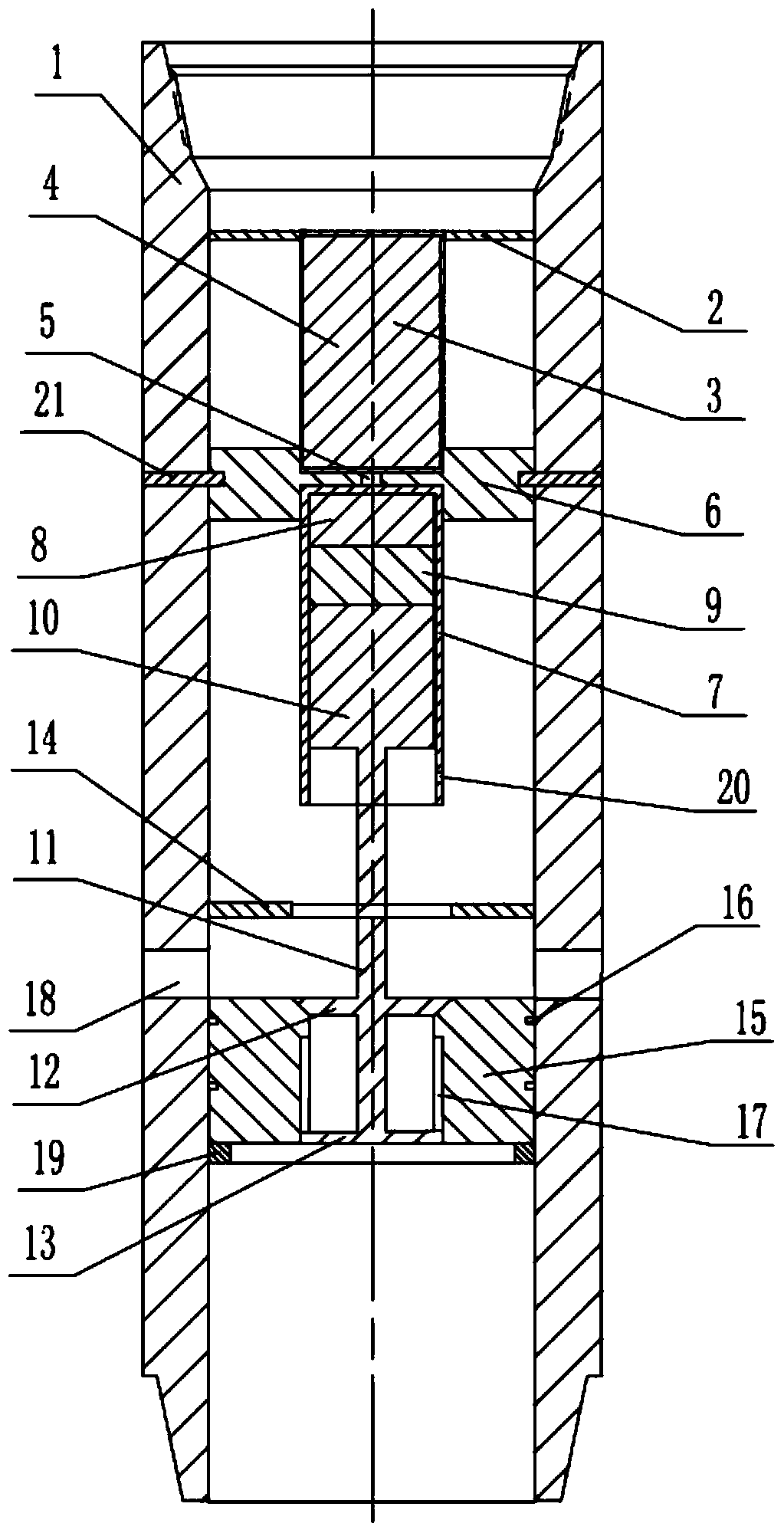
[0028] Such as figure 1 Shown is a specific embodiment of the MWD bypass valve of the present invention. In this embodiment, the bypass valve while drilling mainly includes four parts: a valve body 1 , a control unit, a power unit and an execution unit. Wherein, the valve body 1 is in the shape of a cylinder, and its upper and lower ends are provided with threads for connecting with drilling tools, and the middle part is a through hole. In addition, the control unit, power unit and execution unit are all installed in the valve body 1 .

[0029] In one embodiment, the power unit mainly includes a battery 4 , a battery can 3 , a motor 9 and a transmission assembly 10 . Wherein, the transmission assembly 10 is a screw transmission mechanism. The battery 4 is sealed in the battery can 3, the upper end of the battery can 3 has a centralizing blo...


PUM


Abstract

The invention discloses a while-drilling bypass valve comprising the following elements: a valve body; a power unit connected with the valve body; a control unit electrically connected with a ground controller, the control unit is electrically connected with the power unit, and used for receiving a ground control signal so as to control motions of the power unit; an execution unit arranged in the valve body and connected with the power unit, thus opening and closing the bypass valve. The while-drilling bypass valve is simpler in operation, less in quick wear parts, and can be opened / closed for more times.

Description

technical field [0001] The invention relates to the technical field of drilling, in particular to a bypass valve while drilling. Background technique [0002] During the drilling of oil, natural gas, shale gas and coalbed methane, complex situations such as lost circulation, well overflow and water hole plugging are often encountered. When lost circulation occurs, due to the small size of the drill bit nozzle, the plugging material cannot pass through or may easily cause water hole plugging, and it is necessary to trip out the drill to replace the drilling tool assembly for the plugging operation, resulting in large mud loss and prolonged drilling cycle. In the environment of high-density drilling fluid, the water hole is easy to be blocked. If the well killing operation is carried out at this time, it is necessary to trip out the drill to replace the drilling tools, which may easily cause well overflow and well kick. When dealing with these complex situations, it is necess...

Claims


Application Information

Patent Timeline
Patent Type & Authority Patents(China)
IPC IPC(8): E21B34/14E21B21/10
Inventor 刘鹏马东军曾义金郑俊华陶兴华牛新明王磊孙明光索忠伟张海平陈军海
Owner CHINA PETROLEUM & CHEM CORP
Learn More