Flattop chamfering and cutting device

A cutting device and chamfering technology, applied in the field of steel pipe manufacturing, can solve the problems of inaccurate positioning of tools and floating flanges, easy generation of ripples on the vibrating groove of the tool shank, which is not conducive to realizing cutting automation, etc., and achieves compact structure, low cost, Create easy effects

Inactive Publication Date: 2016-05-11
SUNYO S&T CO LTD
View PDF8 Cites 3 Cited by
  • Summary
  • Abstract
  • Description
  • Claims
  • Application Information

AI Technical Summary

Problems solved by technology

The floating amount of the floating roller with this lever type structure is small, the positioning of the tool and the floating wheel is not accurate, and the tool feeding is carried out by the operator while observing, which is not conducive to the realization of cutting automation
In addition, the groove knives and the blunt edge knives arranged in opposite directions are far away, and it is inconvenient to operate when adjusting the knives
Since the blade is installed on the cutter bar, when processing thick-walled steel pipes, due to the large cutting force, the vibrating groove of the tool bar is prone to ripples

Method used


Image

  • Flattop chamfering and cutting device
  • Flattop chamfering and cutting device
  • Flattop chamfering and cutting device

Examples


Embodiment Construction

[0023] The specific implementation manner of the present invention will be described below in conjunction with the accompanying drawings.

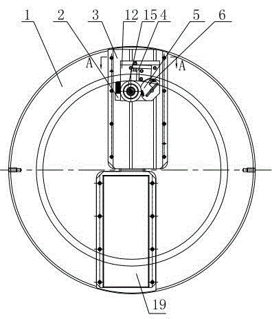
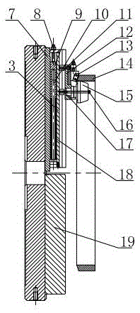
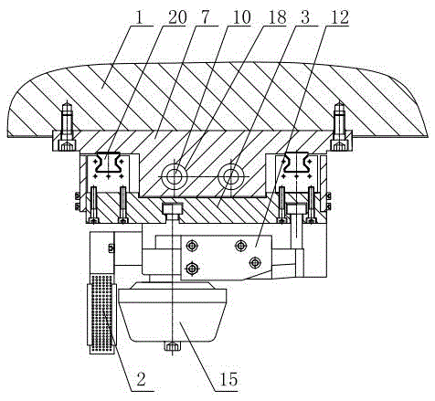
[0024] Such as figure 1 , figure 2 and image 3 As shown, the flat head chamfering cutting device of this embodiment includes a cutter head 1, and a cutting device and a balance weight 19 are symmetrically installed on the cutter head 1. Linear guide rails 20 are respectively installed at both ends of the base plate 7, and a floating seat 3 is installed through the linear guide rails 20 on the base plate 7. There are also holes symmetrically in the middle of the base plate 7. Disc springs 18 are respectively installed in the holes, and guide rods 10 are installed in the middle of the disc springs 18. , a guide block 9 is installed on the top of the guide rod 10, and a pre-tightening screw 8 is installed on the top of the guide block 9; the floating seat 3 slides along the linear guide rail 20, and a T-shaped groove is opened on the floa...


PUM


Abstract

Disclosed is a flattop chamfering and cutting device. The flattop chamfering and cutting device comprises a cutter disc. A cutting device and a balance block are symmetrically disposed on the cutter disc. The cutting device comprises a bottom plate fixed to the cutter disc; linear guide ways are mounted at the two ends of the bottom plate correspondingly; a floating seat is disposed on the bottom plate through the linear guide ways; holes are symmetrically formed in the middle of the bottom plate; belleville springs are disposed in the holes correspondingly; guide rods are mounted in the middles of the belleville springs; guiding blocks are mounted on tops of the guide rods, and pre-tightening screws are mounted on tops of the guiding blocks; the floating seat slides along the linear guide ways; a T-shaped groove is formed in the floating seat; a sliding seat is mounted on the floating seat through a locking block; a beveled edge cutter seat is mounted on the upper portion of the sliding seat; a beveled edge blade is mounted on the beveled edge cutter seat; a depended wheel is arranged on the lower portion of the sliding seat through a shaft and locked through compression screws; a steel wire brush is mounted in the position, on one side of the depended wheel, of the sliding seat; a blunted edge cutter seat is further disposed on the lower portion of the sliding seat; and a blunted edge blade is disposed on the blunted edge cutter seat. The flattop chamfering and cutting device is good in cutting quality.

Description

technical field [0001] The invention relates to the technical field of steel pipe manufacturing, in particular to a flat head chamfering cutting device. Background technique [0002] The bevel processing of pipe end is an important process on the steel pipe manufacturing production line, and the forms of bevel are becoming more and more diversified. The common ones are the combination of single bevel and blunt edge, the combination of compound bevel and blunt edge, and the flat end processing of pipe end. In the prior art, the cutter head is usually used to install two cutting tools upwards in the processing method, one of which is installed on the floating tool holder with a lever-type floating roller to process the bevel, and a fixed tool is installed on the opposite side to process the blunt edge . The floating amount of the floating roller of this lever type structure is small, the positioning of the cutter and the floating wheel is inaccurate, and the cutting tool is c...

Claims


Application Information

Patent Timeline
Patent Type & Authority Applications(China)
IPC IPC(8): B23B5/16B23B25/06
CPCB23B5/16B23B5/161B23B25/06
Inventor 徐伟张建军蒋燕飞盛金周志伟耿东陈文宝
Owner SUNYO S&T CO LTD
Why Eureka
Try Eureka