Pressure casting real-time monitoring device in mould cavity
A technology of real-time monitoring and cavity, which is applied in the field of die-casting, can solve the problems of loss of fluidity and pressure transmission ability, ineffective transmission of casting pressure, lack of verification and real-time monitoring, etc., and achieve the effect of improving precision and product efficiency
- Summary
- Abstract
- Description
- Claims
- Application Information
AI Technical Summary
Problems solved by technology
Method used
Image
Examples
Embodiment 1
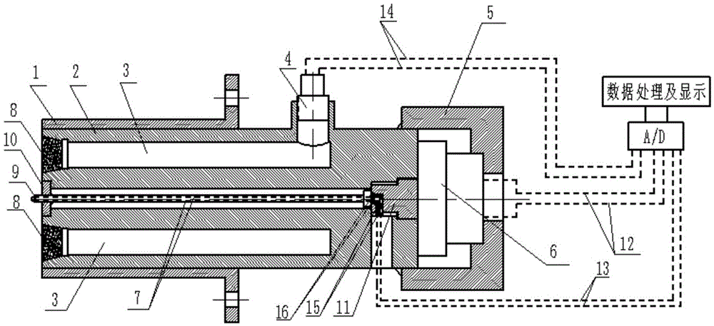
[0025] like figure 1 As shown, according to an embodiment of the invention, a die-casting real-time monitoring device is provided,
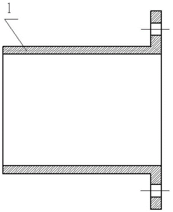
[0026] First of all, its basic components are composed of valve core 2, valve sleeve 1, and valve seat 5. Valve sleeve 1 is fixed on the mold through screw holes on the flange side. The outer wall of valve core 2 cooperates with the inner wall of valve sleeve 1. The front end is used as the molding surface of the mold cavity, and the structure of the valve seat 5 is as follows Figure 4 As shown, the valve seat 5 is a concave cavity structure, and the inner side of the concave cavity cooperates with the outer wall of the valve core 2 to support the valve core 2, and at the same time, it can ensure that the valve core 2 can slide back and forth freely. The stepped holes in the axial direction communicate with each other, and the stepped holes are used to place and fix the second pressure sensor 22. When the valve core 2 receives the pressure from...
Embodiment 2
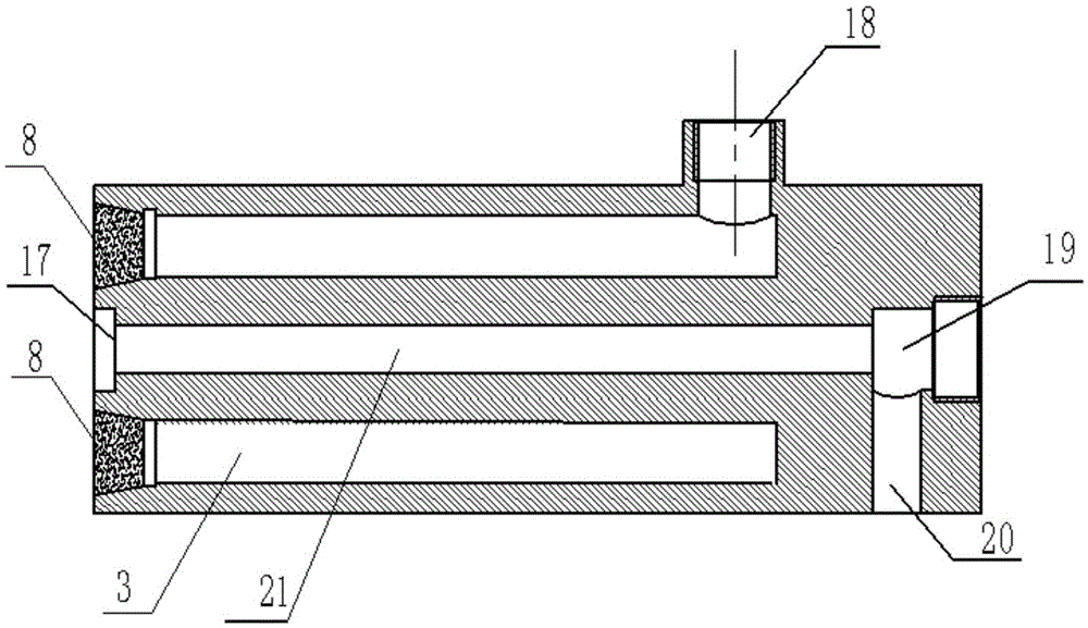
[0029] like figure 1 As shown, first of all, its basic components are composed of valve core 2, valve sleeve 1, and valve seat 5. Valve sleeve 1 is fixed on the mold through screw holes on the flange side, and the outer wall of valve core 2 cooperates with the inner wall of valve sleeve 1. The front end of the valve core 2 is used as the molding surface of the mold cavity, where two gas overflow holes 3 are symmetrically opened with the axis of the valve core 2 as the center line, and the front end of the gas overflow hole 3 is formed into a trumpet-shaped expansion structure. The filter 8 is placed to prevent the aluminum liquid from entering the gas discharge hole 3, and the rear end has an upward first pressure sensor fixing hole 18 that communicates with the outside world. The gas overflow hole 3 is directly connected to the mold cavity, and the end of the gas overflow hole is equipped with a first pressure sensor 4. According to the principle of the connecting chamber, th...
Embodiment 3
[0031] In order to better combine the above-mentioned measurement method with temperature measurement, in this embodiment, in addition to the technical means adopted in Embodiment 1 and Embodiment 2, a temperature measurement method is also added at the same time, A through hole for setting a thermocouple tube 9 is provided at the axis of the valve core 2, and a thermocouple fixing seat 11 is provided at the end of the valve core 2. The thermocouple tube 9 is composed of a thermocouple shell and a thermocouple wire. The metal wire is exposed and can be directly in contact with the molten metal; the thermocouple tube 9 is fixed with a thermocouple tube fixing table 10 at the front end of the valve core 2, and the other end of the thermocouple tube 9 is fixed in the thermocouple fixing seat hole 19, wherein the circle The disc-shaped thermocouple tube fixing platform 10 cooperates with the thermocouple fixing platform hole 19 of the valve core 2 to jointly play the role of fixing...
PUM
 Abstract
Description
Claims
Application Information
 - R&D Engineer
- R&D Manager
- IP Professional
- Industry Leading Data Capabilities
- Powerful AI technology
- Patent DNA Extraction
Browse by: Latest US Patents, China's latest patents, Technical Efficacy Thesaurus, Application Domain, Technology Topic, Popular Technical Reports.
© 2024 PatSnap. All rights reserved.Legal|Privacy policy|Modern Slavery Act Transparency Statement|Sitemap|About US| Contact US: help@patsnap.com


