
Radiator tank for a motor vehicle

A technology for motor vehicles and water tanks, applied in vehicle components, heating/cooling equipment, air handling equipment, etc., can solve problems such as large resistance of steering devices, and achieve the effect of reducing resistance, reducing energy consumption, and avoiding flow interruptions

Active Publication Date: 2016-05-04
WEIDMANN PLASTICS TECH
View PDF9 Cites 0 Cited by
  • Summary
  • Abstract
  • Description
  • Claims
  • Application Information

AI Technical Summary

Problems solved by technology

However, in the case of humid air, the steering device causes a relatively large drag

Method used


Image

  • Radiator tank for a motor vehicle
  • Radiator tank for a motor vehicle
  • Radiator tank for a motor vehicle

Examples


Embodiment Construction

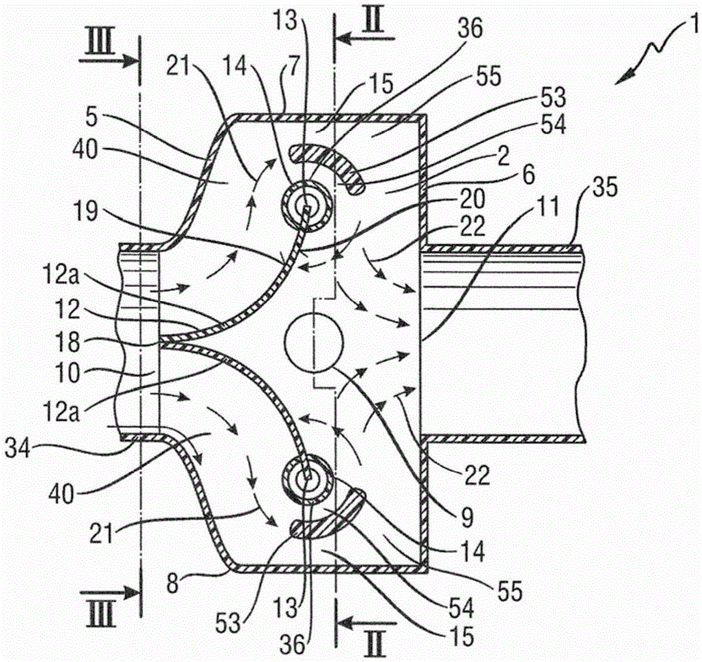
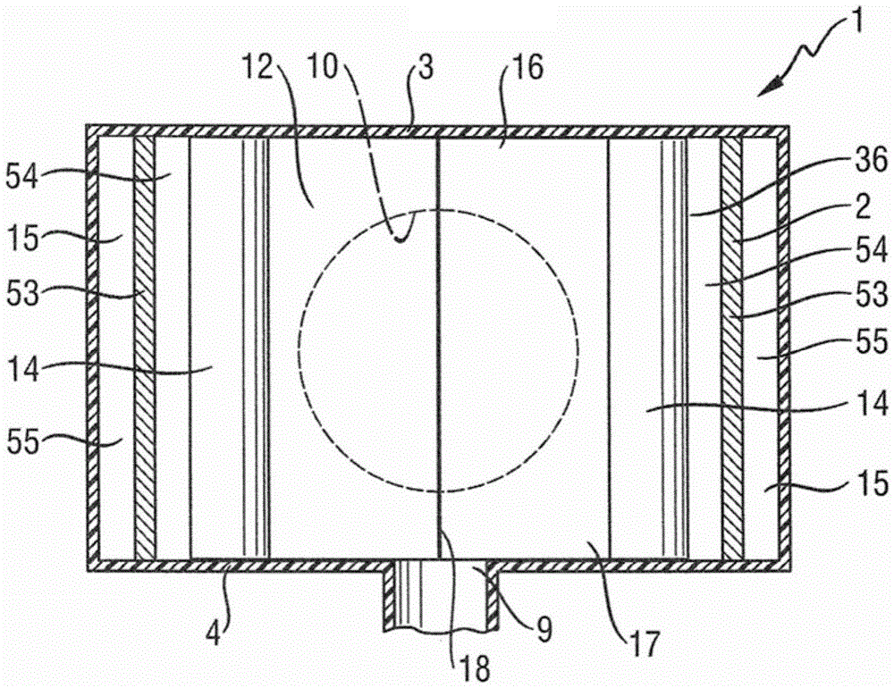
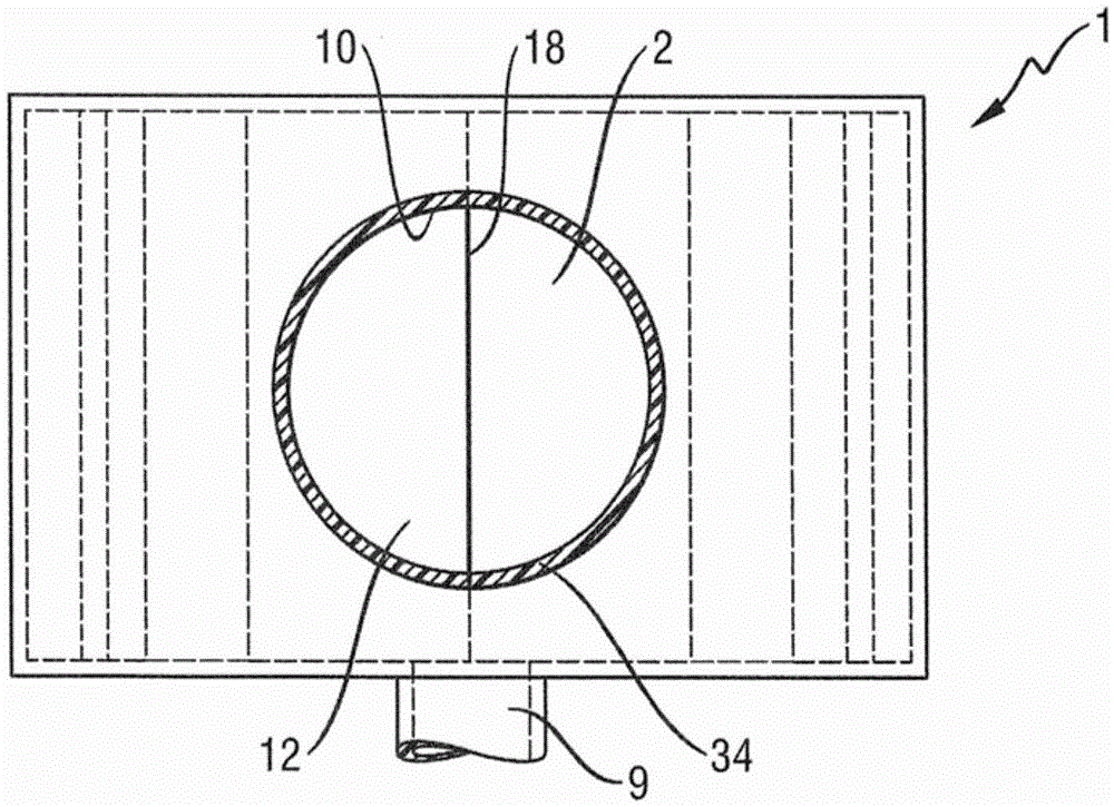
[0046] exist Figures 1 to 4 The cistern 1 shown in has a deflection chamber 2 with a top wall 3 , a bottom wall 4 , a front wall 5 , a rear wall 6 and two side walls 7 and 8 running essentially parallel to one another. The front wall 5 has an air inlet 10 at which sucked-in fresh air can be introduced into the deflection chamber 2 . The front wall 5 is connected via a pipe 34 to a suction opening (not shown here), which is arranged, for example, below the windshield and is covered by a grid (not shown here). The tube 34 can be circular in cross-section as shown. However, the cross section of the tube 34 forming the inlet connection can also have another shape, for example it can be rectangular. The air inlet 10 can also extend over the entire height of the front wall 5 . exist figure 1 , the air thus flows from left to right into the deflection chamber 2 . The transition regions between the tube 34 and the front wall 5 and between the front wall 5 and the side walls 7 an...


PUM


Abstract

The invention provides a radiator tank for a motor vehicle. The radiator tank comprises a deflection chamber (2) comprising a top wall (3); a bottom wall (4) having a water outflow hole (9); an air inlet hole (10); and an air outlet hole (11). Inside the deflection chamber (2) a deflection element (12) is arranged, by which air charged with water droplets and flowing in through the air inlet opening (10) is deflected. The air inlet opening (10) is arranged in the top wall (3) and / or in a front wall (5) and the air outlet opening (11) is arranged in the top wall (3) and / or in a rear wall (6). A flow hole (15) is arranged between at least one side wall (7, 8) of the deflection chamber (2) and a side edge (36) of the deflection element (12). Near said flow hole (15) at least one guide structure (53) is provided to guide air flowing through the deflection chamber (2) around the side edge (36) of the deflection element (12).

Description

technical field [0001] The invention relates to a water tank for a motor vehicle. Background technique [0002] Such radiators are arranged in motor vehicles, in particular under the engine hood, and are used to supply the air-conditioning system in the vehicle interior with fresh air from the environment. For example, the fresh air sucked in when it rains is loaded with water droplets. In addition, splash water can enter the water tank through the suction opening. In order to be able to supply the air-conditioning system with the dryest possible air, not only splashes from the fresh air but also water droplets or particulate matter are guided as efficiently as possible into the drain openings in the bottom wall in the water tank and discharged there. The efficiency of the water separation should be as high as possible, so that as few water droplets as possible get into the vehicle interior and in particular into the air filter of the air conditioning system. An increasin...

Claims


Application Information

Patent Timeline
IPC IPC(8): B60H1/28
CPCB60H1/28
Inventor 科林·恰内利克里斯蒂安·博埃尔斯特利皮耶罗·达尔韦基奥阿明·穆勒
Owner WEIDMANN PLASTICS TECH
Learn More