Stabbing metal ware

A technology of fittings and core tubes, applied in the field of overhead line power fittings, can solve problems such as easy loosening and poor firmness, and achieve the effects of reasonable center of gravity distribution, labor-saving operation, and good anti-loosening effect

Active Publication Date: 2016-05-04
李建勋
View PDF3 Cites 0 Cited by
  • Summary
  • Abstract
  • Description
  • Claims
  • Application Information

AI Technical Summary

Problems solved by technology

However, traditional hardware also has shortcomings. The pressure of clamping wire depends on the pressure of ordinary bolt components, which is poor in firmness and easy to loosen.

Method used


Image

  • Stabbing metal ware
  • Stabbing metal ware
  • Stabbing metal ware

Examples


Embodiment 1

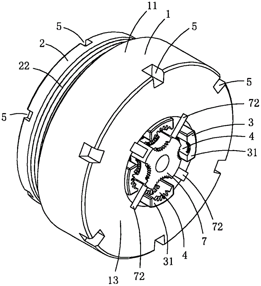
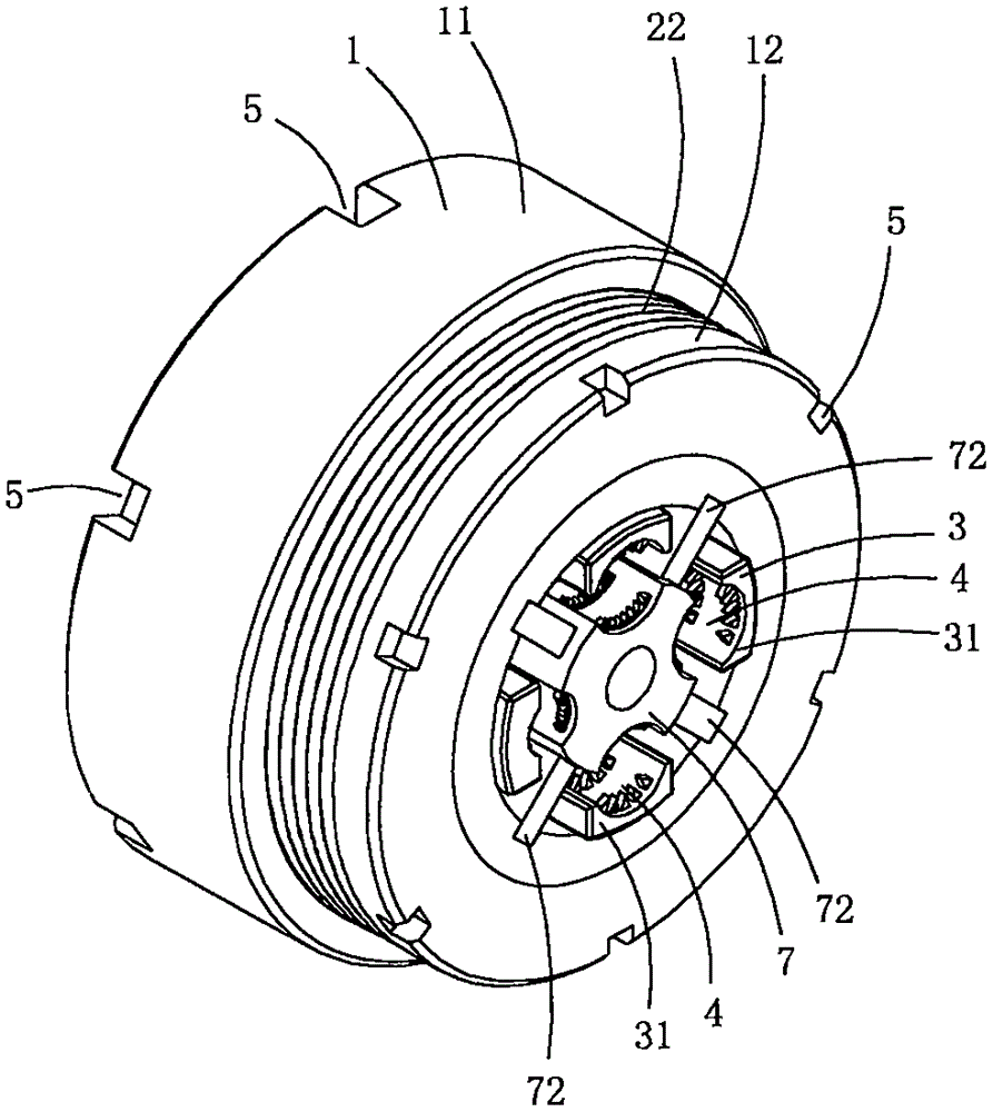
[0015] This embodiment is a kind of puncture gold tool, see Figure 1 to Figure 6 As shown, it includes a base body 1 , a pressure ring 2 , a mandrel 7 and a set of pressure jaw assemblies 3 .

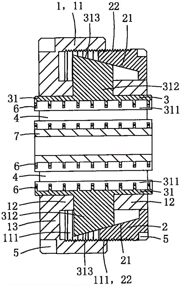
[0016] The base body 1 includes a base pipe part 11 provided with an internally threaded area 111, a core pipe part 12 arranged in the lumen of the base pipe, and a connecting plate part 13 for connecting and fixing the base pipe part and the core pipe part; the base pipe part and the core The tube parts are arranged concentrically, and the connecting plate part is an annular plate located between the base tube part and the core tube part. In this embodiment, the connecting plate part is located at the edge of the same side of the base tube part and the core tube part; The structural shape only needs to satisfy the fixed connection between the base pipe part and the core pipe part.

[0017] The base pipe part, the core pipe part and the connecting plate part in this embodiment are int...

Embodiment 2

[0033] This embodiment is basically the same as Embodiment 1, the difference is: see Figure 7 As shown, this embodiment also includes a voltage transformer 8; the voltage transformer includes an annular induction body 81 and an intelligent control module; in this embodiment, the connecting plate is provided with an annular groove, and the annular induction body of the voltage transformer and the intelligent control module The control module is fixed in the annular groove. In specific practice, the voltage transformer can also be fixedly arranged on the tube wall of the core tube part, as long as the clamping hole is located in the cavity of the ring-shaped induction body, that is, it is only necessary to make the cable pass through the ring-shaped induction body The cavity is enough.

[0034] The intelligent control module can include a wireless transceiver unit, through which the intelligent control module transmits the secondary voltage or current signal sensed by the annu...


PUM


Abstract

The invention discloses a stabbing metal ware, comprising a base body, a pressing ring and a set of pressing jaw assembly; the base body comprises a base tube part with an inner thread area, a core tube part and a connection plate part; multiple guide slide holes are arranged on the tube wall of the core tube part; the pressing jaw assembly comprises multiple pressing jaws; every pressing jaw is equipped with a pressing plate part and a guide slide post part; the guide slide post parts are formed by projecting from the pressing plate parts; the top end of every guide slide post part is equipped with a stress inclined plane; the pressing plate part of every pressing jaw is located in the tube cavity of the core tube part; every guide slide post part penetrates a corresponding guide slide hole, stretches out of the outer side of the core tube part and is located in the tube cavity of the base tube part; the pressing ring comprises a conical press-connection face arranged on the inner peripheral wall of the pressing ring and an outer threaded area arranged on the outer peripheral wall of the pressing ring; the conical press-connection face of the pressing ring and the stress inclined plane of every pressing jaw are in press connection; the outer thread area of the pressing ring fits with the inner thread area of the base tube part; the pressing ring pushes the pressing plate part of every pressing jaw to move towards the center of the core tube part. The stabbing metal ware has relatively good mechanical and electrical performance.

Description

technical field [0001] The technical field of electric power fittings for overhead lines of the present invention particularly relates to a piercing fitting. Background technique [0002] In the construction of overhead power lines, when the cables need to be branched or spliced, it is necessary to use fittings to connect two insulated conductors together. Fittings have the characteristics of easy installation, low cost, safety, reliability and maintenance-free. Cable branches can be made without cutting off the main cable or stripping the insulation layer of the cable. The joints are completely insulated and can be used for live work, and can be branched at any position on the cable; no terminal box or junction box is needed; and the joints are resistant to twisting, Shockproof, waterproof, anti-corrosion and aging; using insulating fittings as cable branches, the comprehensive benefits are obvious, and the cost performance is better than the traditional connection methods...

Claims


Application Information

Patent Timeline
Patent Type & Authority Applications(China)
IPC IPC(8): H01R4/24H01R4/28H02G7/00
CPCH01R4/24H01R4/28H02G7/00
Inventor 胡小青
Owner 李建勋
Why Eureka
Try Eureka