Dry etching device

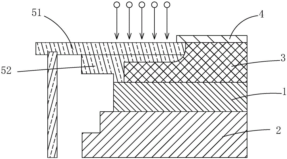
A dry etching and annular protection technology, applied in the manufacture of discharge tubes, electrical components, semiconductor/solid-state devices, etc., can solve the problems of uneven etching of the wafer to be etched or the substrate 4, reduction of plasma energy, etc., and increase the normal operation. time, reduced maintenance costs, and extended service life

Inactive Publication Date: 2016-05-04
WUHAN CHINA STAR OPTOELECTRONICS TECH CO LTD
View PDF7 Cites 7 Cited by
  • Summary
  • Abstract
  • Description
  • Claims
  • Application Information

AI Technical Summary

Problems solved by technology

[0004] When the current electrode plate 1 is the same size as the wafer to be etched or the substrate 4, the energy of the plasma above the edge of the wafer to be etched or the substrate 4 is reduced, resulting in uneven etching of the wafer to be etched or the substrate 4

Method used


Image

  • Dry etching device
  • Dry etching device
  • Dry etching device

Examples


no. 1 example

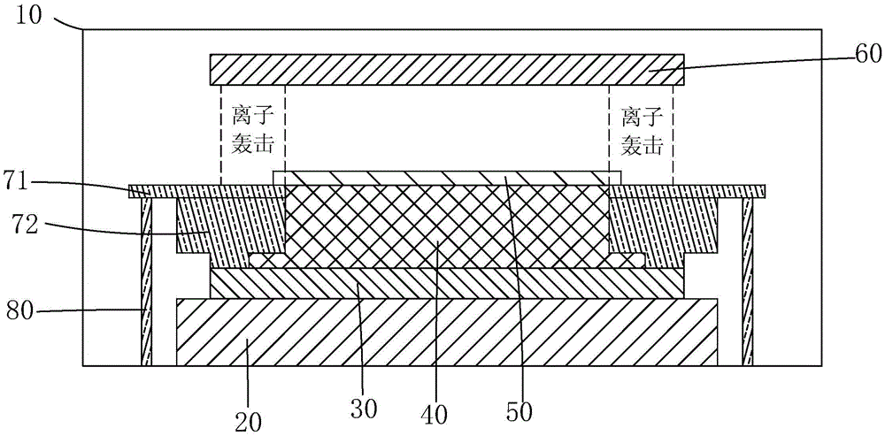
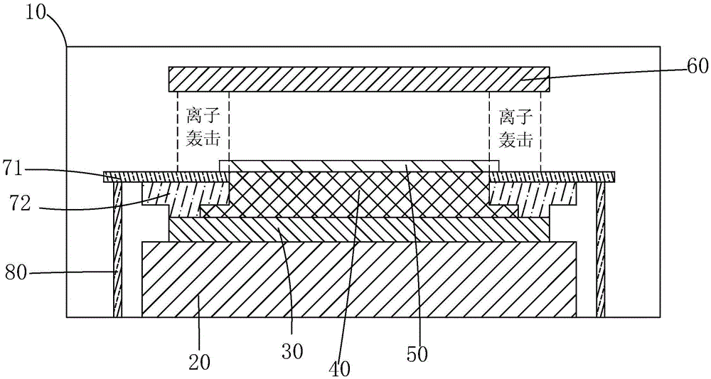
[0026] The invention provides a dry etching device. figure 2 Shown is the first embodiment of the dry etching device of the present invention, comprising: a vacuum chamber 10, an insulating plate 20 disposed in the vacuum chamber 10, a lower electrode plate 30 disposed on the insulating plate 20, and a The electrostatic adsorption platform 40 used to carry the substrate 50 to be etched on the lower electrode plate 30, the upper electrode plate 60 arranged at a distance from the lower electrode plate 30, and the edge protection plate 71 flush with the upper surface of the electrostatic adsorption platform 40 , and an annular protection plate 72 arranged between the edge protection plate 71 and the lower electrode plate 30 to cover the outer periphery of the lower electrode plate 30 and the electrostatic adsorption platform 40 .

[0027] The edge protection plate 71 at least completely covers the ring protection plate 72 , that is, the extension length of the edge protection pl...


PUM


Abstract

The invention provides a dry etching device. Compared with the existing dry etching device, by increasing the thickness of a focus ring (72) under an edge ring (71) for withstanding ion bombardment or reducing the dielectric constant of the material of the focus ring (72) under the edge ring (71) for withstanding ion bombardment, the sheath voltage on the surface of the edge ring (71) is reduced based on the Kirchhoff's law of partial pressure. Therefore, bombardment of ions to the edge ring (71) is weakened, the service life of the edge ring (71) is prolonged, the normal working time of the dry etching device is increased, and the maintenance cost is reduced.

Description

technical field [0001] The invention relates to the technical field of semiconductor manufacturing, in particular to a dry etching device. Background technique [0002] With the development of the information society, people's demand for display devices has increased, which has also promoted the rapid development of the LCD panel industry, and the output of panels has continued to increase. Etching is an important process in the process of manufacturing thin film transistor liquid crystal display (ThinFirmTransistorLiquidCrystalDisplay, TFT-LCD) array substrate process. The etching process is divided into a dry etching process and a wet etching process according to the physical state of the etchant. The dry etching process uses an etching gas for etching, and the wet etching process uses an etching liquid for etching. [0003] Such as figure 1 As shown, the existing dry etching device generally includes: a vacuum chamber (not shown), an upper electrode plate (not shown) ar...

Claims


Application Information

Patent Timeline
Patent Type & Authority Applications(China)
IPC IPC(8): H01J37/32H01L21/67
CPCH01J37/32495H01L21/67069
Inventor 肖文欢
Owner WUHAN CHINA STAR OPTOELECTRONICS TECH CO LTD
Why Eureka
Try Eureka