Eureka AIR delivers breakthrough ideas for toughest innovation challenges, trusted by R&D personnel around the world.

Heating device for liquid heating

A technology for heating devices and liquids, applied in electric heating devices, fluid heaters, water heaters, etc., can solve the problems that the water temperature cannot be constant, the pressure cannot be stored, and the waiting time is long, and the waiting time for startup preheating can be reduced. , The effect of low manufacturing cost and long service life

Active Publication Date: 2016-05-04
FOSHAN VIOMI ELECTRICAL TECH +1
View PDF8 Cites 4 Cited by
  • Summary
  • Abstract
  • Description
  • Claims
  • Application Information

AI Technical Summary

Problems solved by technology

Due to the large thermal inertia of aluminum, there will be the following problems: 1. When starting up, it takes a long time for 15 to 30 seconds (seconds) to warm up before the cast aluminum can be heated to the required temperature; In the case of water, the heat generated by the heating resistance wire cannot keep up with the heat absorbed by the liquid in time, which will cause the temperature of the cast aluminum to drop. If the required water temperature cannot drop, you need to continue to wait for heating; 3. If the heater is in standby, you need to Use the control to keep the temperature of the cast aluminum constant, resulting in a waste of energy; 4. The cast aluminum heater with such a high thermal inertia must be preheated to obtain water at a constant temperature. When the water is continuously discharged, the water temperature cannot be kept constant.
There is no problem with the installation, but it will cause sealing problems, so that the water cannot flow completely in accordance with the flow direction of the liquid channel. There will always be a part of the water that will take a shortcut from the gap that is not tightly sealed. The water flow channel is certain, which will inevitably lead to part of the water not flowing , become stagnant water, and continue to heat there, eventually leading to gasification, resulting in steam ejection, and intermittent water discharge. At the same time, because the seal between the plastic box and the metal can only be sealed by the sealing ring, it cannot meet the requirement of a storage pressure of 8 to 10 bar. In the middle of the pressure, it may also be aging due to the speed or the sealing ring being used in a high temperature environment for a long time, and there is a risk of leakage

Method used


Image

  • Heating device for liquid heating
  • Heating device for liquid heating
  • Heating device for liquid heating

Examples


Embodiment 1

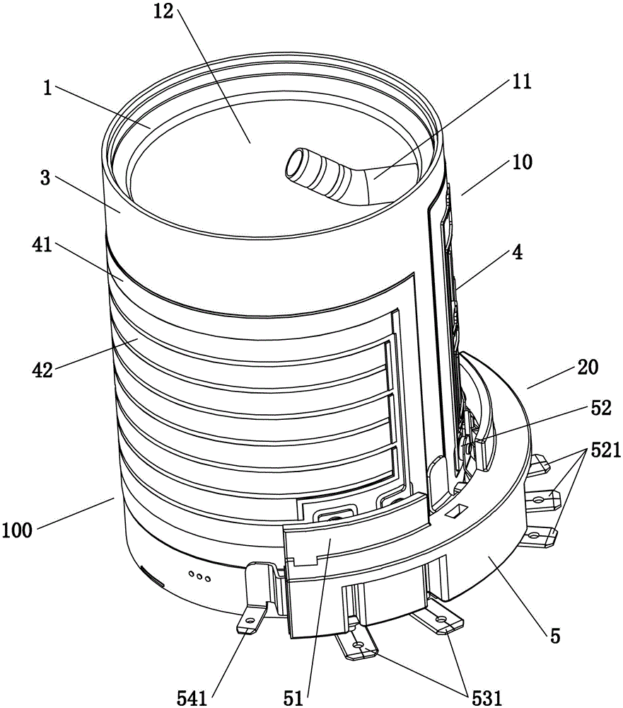
[0034] Embodiment one, see Figure 1 to Figure 5 As shown, a heating device 100 for liquid heating includes a sealing bracket 1, a heating body 10, a water inlet 14 and a water outlet 11, the sealing bracket 1 is sealed and connected to the heating body 10, and a cavity is enclosed between them The cavity is provided with a sealing body 2, and the sealing body 2 and the heating body 10 enclose a sealed waterway 8 with a certain capacity. The sealed waterway 8 communicates with the outside world through the water inlet 14 and the water outlet 11 respectively. The liquid is sealed and confined in the sealed water channel 8 , and finally flows out from the water outlet 11 along the sealed water channel 8 .

[0035] The sealing body 2 is provided with sealing ribs 21 corresponding to the straight communication path between the water inlet 14 and the water outlet 11 , and the sealing ribs 21 are sealingly matched with the heating body 10 . The sealing rib 21 is integrally formed w...

Embodiment 2

[0051] Embodiment two, the difference with embodiment one is: see Figure 6 As shown, the surface of the sealing bracket 1 is provided with a positioning portion 15 for defining the installation position of the sealing body. The positioning portion 15 is more than two convex points or ribs.

[0052] combine Figure 7 As shown, a water purification system with the above heating device 100 includes a filter assembly 9, a flow regulating device 30 and a heating device 100, the heating device 100 is provided with a water inlet 14 and a water outlet 11, the filter assembly 9, the flow regulating device 30 and the heating device 100 are connected in series through a waterway, and the filter assembly 9 is arranged on the waterway before the water inlet 14 .

[0053] It also includes an inlet water temperature detection device (inlet water temperature sensor 40), the filter assembly 9 includes a raw water area 91, a filter device 92 and a water purification area 93, and the raw wate...


PUM


Abstract

The invention relates to a heating device for liquid heating. The heating device comprises a sealing support, a heating body, a water inlet and a water outlet. The sealing support and the heating body are in sealed connection. A cavity is defined by the sealing support and the heating body. A sealing body is arranged inside the cavity. A sealing water channel with the certain capacity is defined by the sealing body and the heating body. The sealing water channel is communicated with the external world through the water inlet and the water outlet. Liquid entering the water inlet is sealed and limited inside the sealing water channel and flows out of the water outlet along the sealing water channel. According to the heating device, the starting-up preheating waiting time can be shortened, the continuous water outlet temperature is stable, and the temperature of cast aluminum does not need to be maintained by means of heating during standby; meanwhile, the problems that water outlet steam and non-continuous water outlet are caused by gasification due to the water circulating problem caused by a gap between a liquid flow pass and a stainless steel thick film heater can be avoided.

Description

technical field [0001] The invention relates to a heating device, in particular to a heating device for liquid heating. Background technique [0002] Generally, in heating appliances that require continuous hot water, the heating resistance wire is wrapped or filled with an insulating layer and embedded in cast aluminum with good thermal conductivity. At the same time, the stainless steel tube is bent to form a continuous liquid flow channel. in cast aluminum. [0003] Because the heat generated by the heating resistor cannot directly exchange heat with water, the cast aluminum needs to be heated to a certain temperature first, and the heat on the cast aluminum passes through the stainless steel tube liquid channel to generate heat exchange with water. Due to the large thermal inertia of aluminum, there will be the following problems: 1. When starting up, it takes a long time for 15 to 30 seconds (seconds) to warm up before the cast aluminum can be heated to the required te...

Claims


Application Information

Patent Timeline
Patent Type & Authority Applications(China)
IPC IPC(8): F24H1/10F24H9/18F24H9/20
CPCF24H1/103F24H9/1818F24H9/2028F24H1/162F24H9/0015H05B3/262H05B3/46H05B2203/003H05B2203/01H05B2203/013H05B2203/016H05B2203/021
Inventor 陈小平
Owner FOSHAN VIOMI ELECTRICAL TECH
Why Eureka
Eureka Blog
Learn More