
Parabolic trough solar thermal power generation system and method utilizing fuse salt medium

A trough solar and thermal power generation system technology, applied in the field of solar energy utilization, can solve problems such as difficulty in improving power generation efficiency, increasing system cost, and easy solidification of molten salt, reducing configuration complexity, reducing system cost, and improving safety. Effect

Inactive Publication Date: 2016-05-04
中广核太阳能开发有限公司 +1
View PDF4 Cites 25 Cited by
  • Summary
  • Abstract
  • Description
  • Claims
  • Application Information

AI Technical Summary

Problems solved by technology

It can be seen that the traditional trough solar thermal power generation system uses heat-conducting oil as the heat-collecting medium, molten salt as the heat-storage medium, and water vapor as the power-generating medium; since the upper limit of the temperature of the heat-conducting oil is 400 degrees, the trough It is difficult to improve the power generation efficiency due to the steam temperature and pressure parameters of solar thermal power generation; in addition, due to the use of three media, the trough solar thermal power generation system needs to be equipped with an oil-salt heat exchanger and an oil-water heat exchanger, which increases the system cost
[0003] In order to solve the above problems, some research and development institutions in the world have also developed trough solar thermal power generation systems that use molten salt media as both heat collection and heat storage media. However, due to the high freezing point of molten salt, molten salt is very easy to solidify, thus Catastrophic accidents for the cycle of the entire trough solar thermal power generation system
Based on this, there is currently no successful trough solar thermal power generation system using molten salt medium in the world.

Method used


Image

  • Parabolic trough solar thermal power generation system and method utilizing fuse salt medium
  • Parabolic trough solar thermal power generation system and method utilizing fuse salt medium

Examples


Embodiment Construction

[0037] The present invention is described in detail below in conjunction with accompanying drawing:

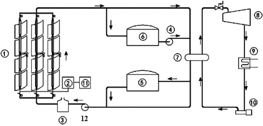
[0038] Such as figure 1 As shown, the present invention provides a trough solar thermal power generation system using a molten salt medium, including a trough collector 1, a brine heat exchanger 7, a turbo generator 8, a low-temperature heat storage tank 5, and a high-temperature heat storage tank 6 and exhaust molten salt system;

[0039] The salt outlet of the trough collector 1 is divided into two branches, one branch is directly connected to the salt inlet of the brine heat exchanger 7, and the other branch is connected to the salt inlet of the high-temperature heat storage tank 6; The salt outlet of the heat storage tank 6 is connected to the salt inlet of the brine heat exchanger 7 through the first molten salt pump 4; The exhaust port of 7 is connected to the air inlet of turbo-generator 8, the exhaust port of steam-turbine generator 8 is connected to the air inlet of...


PUM


Abstract

The invention provides a parabolic trough solar thermal power generation system and method utilizing a fuse salt medium. The system comprises a trough heat collector (1), a saline water heat exchanger (7), a turbo-generator (8), a low-temperature heat accumulating tank (5), a high-temperature heat accumulating tank (6) and a fuse salt discharging system. The trough heat collector (1) is composed of a plurality of columns of independent sub-trough heat collectors, and each sub-trough heat collector is formed by connecting a plurality of heating collecting pipes from bottom to top in sequence. Each sub-trough heat collector is provided with at least one salt discharging pipeline, wherein one end of each salt discharging pipeline is communicated with a cavity of the corresponding sub-trough heat collector, and the other end of each salt discharging pipeline is connected with a salt storage tank. Control valves are installed at the ends, close to the sub-trough heat collectors, of the salt discharging pipelines. In addition, the bottom of each sub-trough heat collector is provided with an air inlet. The parabolic trough solar thermal power generation system and method have the beneficial effects that the system cost is low, and the system using safety is high.

Description

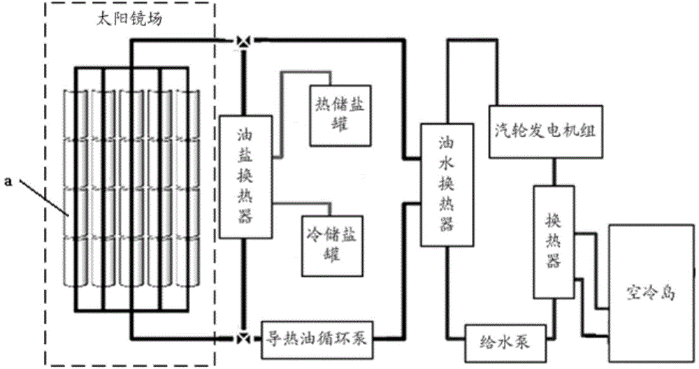
technical field [0001] The invention belongs to the technical field of solar energy utilization, and in particular relates to a trough-type solar thermal power generation system and a thermal power generation method using a molten salt medium. Background technique [0002] The structure of the traditional trough solar thermal power generation system is as follows: figure 1 As shown, heat collector a is arranged in the sun mirror field, and the heat collecting medium in heat collector a is heat transfer oil. Therefore, the sun mirror field gathers sunlight into the heat collector, thereby heating the cold heat transfer oil in the heat collector It is high-temperature heat-conducting oil; the high-temperature heat-conducting oil output from the heat collector flows into the oil-water heat exchanger, exchanges heat with the cooling water, and heats the cooling water into superheated steam, thereby driving the steam turbine to generate power; the cold water output through the oi...

Claims


Application Information

Patent Timeline
IPC IPC(8): F03G6/06
CPCY02E10/46
Inventor 董军
Owner 中广核太阳能开发有限公司
Learn More