
A single-pipe double-layer injection process string for carbon dioxide flooding

A carbon dioxide and process pipe string technology, which is applied in the direction of production fluid, wellbore/well parts, earthwork drilling and production, etc., can solve the problems of difficult construction, high construction cost, and affecting production, so as to avoid maintenance operations and switching Convenience and the effect of saving construction costs

Active Publication Date: 2018-02-13
沈阳华威石油机械制造有限公司
View PDF7 Cites 1 Cited by
  • Summary
  • Abstract
  • Description
  • Claims
  • Application Information

AI Technical Summary

Problems solved by technology

The carbon dioxide layered injection process column in the prior art mostly adopts the CO disclosed in CN 201539215U 2 Concentric double-pipe separate injection process string, this process string consists of inner tubing and outer tubing to form dual channels, since the inner tubing must pass through the outer tubing and then connect with the packer, the construction is difficult, and, once the If a channel fails, carbon dioxide can only be injected into one interval, or the entire pipe string must be pulled out for repairs, which not only affects production, but also requires high construction costs

Method used


Image

  • A single-pipe double-layer injection process string for carbon dioxide flooding
  • A single-pipe double-layer injection process string for carbon dioxide flooding
  • A single-pipe double-layer injection process string for carbon dioxide flooding

Examples


Embodiment Construction

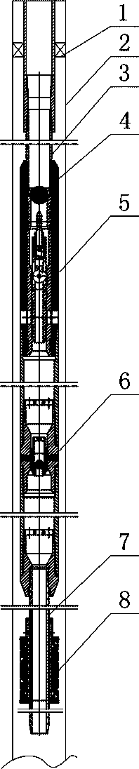
[0014] Such as figure 1 As shown, the string of the single-pipe double-layer injection process for carbon dioxide flooding oil flooding of the present invention includes a casing 2, an oil pipe 3 is arranged in the casing, and a drillable bridge plug 8 is arranged in the casing, and the bridge plug can be drilled to close the casing. It is divided into an upper section and a lower section. A sealing cannula 7 is inserted on the drillable bridge plug. The sealing cannula is preferably a self-supporting formal sealing cannula. There are a setting ball valve 6, a throwing and fishing distribution device 5 and a packer 1.

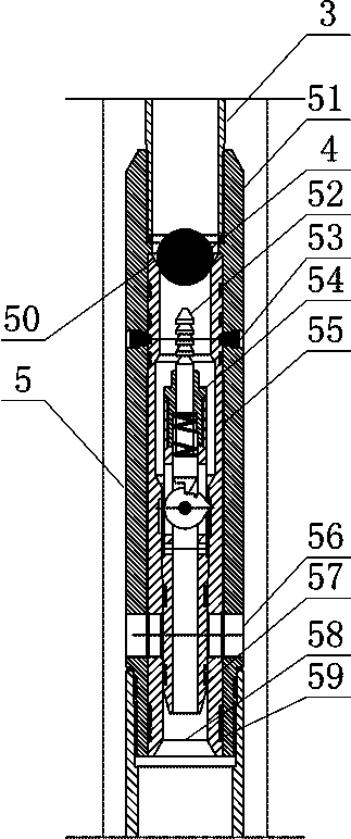
[0015] Such as figure 2 As shown, the fishing-type distribution device includes an outer cylinder 51 connected to oil pipes at both ends, and an inner sliding cylinder 55 that is slidingly and sealingly matched with the inner wall of the outer cylinder is arranged in the outer cylinder, and an inner sliding cylinder is provided on the outer cylinder to preven...


PUM


Abstract

The invention discloses a carbon dioxide wheel injection oil displacement single-tube double-layer injection process tubular column. The carbon dioxide wheel injection oil displacement single-tube double-layer injection process tubular column comprises a casing tube. An oil tube is arranged in the casing tube. The tubular column is characterized in that a drillable bridge plug is arranged in the casing tube, the casing tube is divided into an upper-layer section and a lower-layer section through the drillable bridge plug, a seal insertion tube is inserted into the drillable bridge plug, the upper end of the seal insertion tube is connected with the oil tube, the oil tube is sequentially provided with a setting ball valve, a throwing-in and pulling bottom-hole regulator and a packer from bottom to top, the throwing-in and pulling bottom-hole regulator comprises an outer barrel and an inner sliding barrel, an inner sliding barrel fixing shear pin for preventing the inner sliding barrel from axially sliding in the outer barrel is arranged on the outer barrel, an upper-layer section gas injection port is formed in the outer barrel and the inner sliding barrel, a throwing-in and pulling stopper is further arranged in the inner sliding barrel, a fishing head is arranged on the upper portion of the stopper, and a lower-layer section gas injection nozzle is arranged on the lower portion of the stopper. The process tubular column is simple in structure, construction and injection rate adjustment are convenient, single upper-layer injection, single lower-layer injection and simultaneous two-layer injection can be achieved, and work can continue in a sweeping injection mode after one-layer injection failure.

Description

technical field [0001] The invention relates to an oilfield process string, in particular to a single-pipe double-layer injection process string used for injecting carbon dioxide into an oil field. Background technique [0002] In the process of carbon dioxide flooding, it is necessary to inject carbon dioxide into the oil layer by using the pipe string. Due to the difference in the permeability of each oil layer, it is necessary to use the layered injection technology first. The carbon dioxide layered injection process column in the prior art mostly adopts the CO disclosed in CN 201539215U 2 Concentric double-pipe separate injection process string, this process string consists of inner tubing and outer tubing to form dual channels, since the inner tubing must pass through the outer tubing and then connect with the packer, the construction is difficult, and, once the If a channel breaks down, carbon dioxide can only be injected into one layer, or the entire pipe string must...

Claims


Application Information

Patent Timeline
Patent Type & Authority Patents(China)
IPC IPC(8): E21B43/16E21B43/14E21B34/08E21B34/14
CPCE21B34/063E21B34/08E21B34/14E21B43/14E21B43/164E21B2200/04E21B2200/06
Inventor 周淼廉军赵元
Owner 沈阳华威石油机械制造有限公司
Learn More