
Circulating lifting device

A technology of lifting equipment and reversing device, which is applied in the direction of buildings, building types, buildings, etc. where cars are parked, can solve the problems, characteristics and advantages of equipment stability that must be supplemented in the patent of the present invention and have not been well solved Incomprehensible narration and other issues to achieve the effect of high work efficiency

Active Publication Date: 2016-05-04
BEIHANG UNIV
View PDF8 Cites 8 Cited by
  • Summary
  • Abstract
  • Description
  • Claims
  • Application Information

AI Technical Summary

Problems solved by technology

In the process of in-depth discussion, we think that these two patents still have the following deficiencies: First, it was previously believed that the circulation lifting equipment is only a general handling equipment, so it is named new circulation transportation equipment and circulation elevator. In fact, it is a kind of Multifunctional general-purpose mechanical equipment; secondly, the characteristics and advantages of the present invention patent are not comprehensively described in the first two patents, and must be re-expressed in the present invention patent; thirdly, the present invention patent has basic type and energy-saving type The first two patents only describe the basic type and the energy-saving type of circulating lifting equipment, and the comprehensive and high-efficiency circulating lifting equipment must be supplemented in the patent of the present invention. ; Fourth, in the first two patents, the stability problem of the equipment during operation is not well solved

Method used


Image

  • Circulating lifting device
  • Circulating lifting device
  • Circulating lifting device

Examples


Embodiment Construction

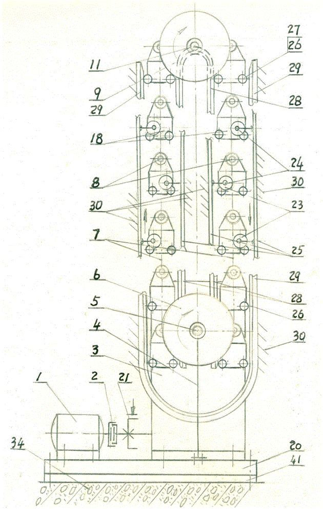
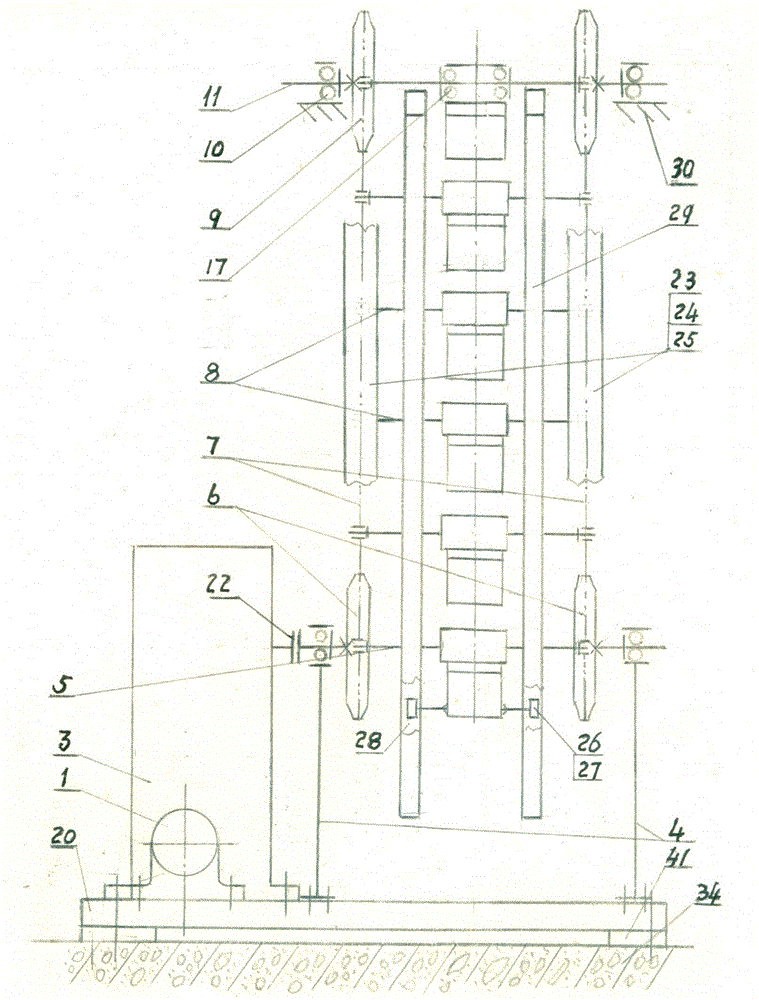
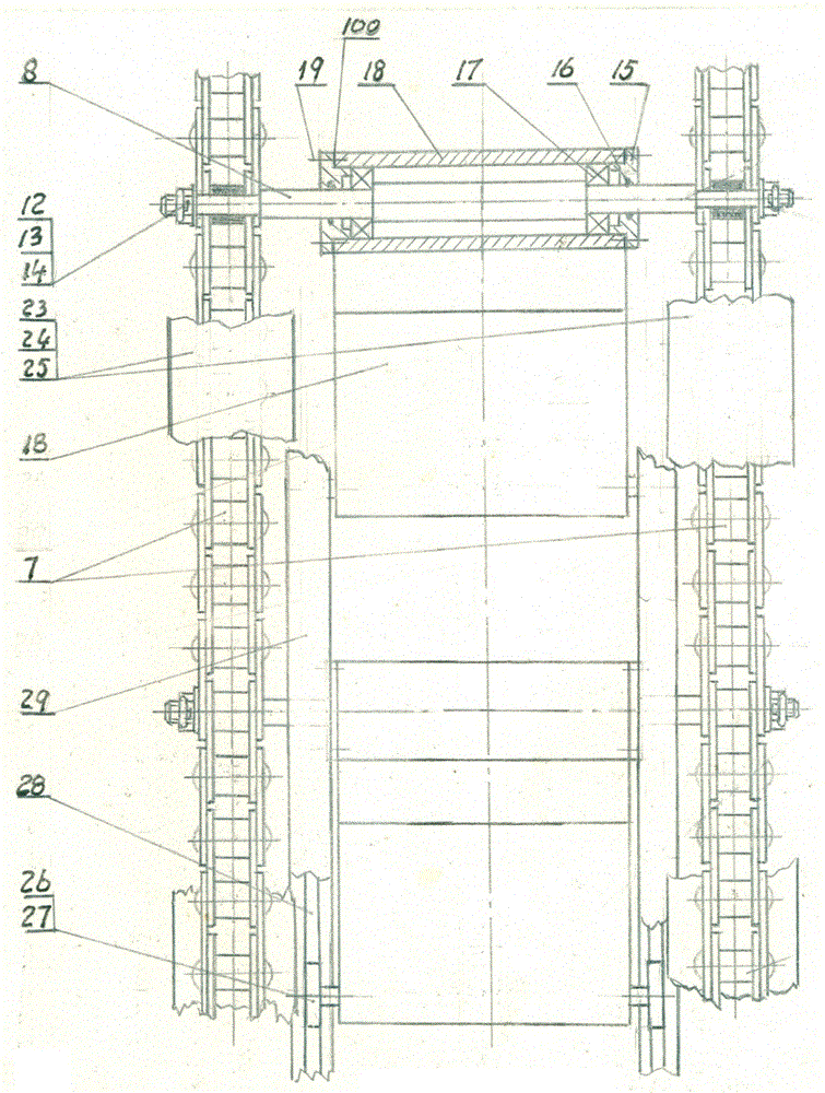
[0057] In the following text expressions, we will refer to the basic circulation lifting equipment as basic equipment, the energy-saving circulation lifting equipment as energy-saving equipment, the comprehensive circulation lifting equipment as comprehensive equipment, and the high-efficiency circulation lifting equipment as high-efficiency Equipment, the four are collectively referred to as equipment. In order to save space, reduce drawings, and explain the problem, I will mainly introduce and explain the principle, structure and application of the patent of the present invention based on the basic equipment, and only talk about the differences from the basic equipment for other equipment.

[0058] Depend on figure 1 , 2 , 3, 4, it can be seen that the basic equipment involved in the patent of the present invention includes a motor 1, a clutch 2, a brake 21, a worm gear gearbox 3, and the output shaft of the worm gear gearbox 3 is equipped with a coupling 22, which Connect...


PUM


Abstract

Provided is a circulating lifting device. A transmission device is installed on ground, a reversing device is installed on another fixed object, and two chains connect the transmission device and the reversing device. A rotating shaft is connected with the two chains. A moving box is installed on the middle part of the rotating shaft in a vertical oscillating manner. Driven by the transmission device, the device realizes circulation, roundtripping, carrying, loading and unloading, and storage of personnel, materials and goods, and materials. The device is formed by the transmission device, the reversing device, a carrying device, and a stabilizing device. The circulating lifting device has four types. The types are a basic circulating lifting device, an energy-efficient circulating lifting device, a comprehensive circulating lifting device, and an efficient circulating lifting device. The common characteristics are that through changing the structure, the number, and operating methods (circulating or reciprocating motion), circulating paths of the moving box, and changing placing methods (vertical, inclined, horizontal, reversed inclined, and reversed) of the moving boxes, the device has new purposes and becomes a new product. Mechanical equipment manufactured according to principles of the equipment has characteristics of high efficiency, energy conservation, land saving, and cost saving, and the equipment is suitable for automation production in large batch.

Description

technical field [0001] The patent of the present invention relates to a multi-purpose mechanical equipment, in particular to a circulation lifting equipment integrating storage and transportation, loading and unloading, house building, water lifting, entertainment and national defense. Background technique [0002] Existing circulation lifting equipment includes water wheel, ferris wheel, vertical circulation type three-dimensional parking garage, new circulation transportation equipment and circulation elevator. [0003] The waterwheel is an ancient tool for carrying water. Made of wood, the water lifting efficiency is low and easy to wear. In remote areas, due to lack of electricity, it is still in use, and other areas have been replaced by water pumps. The water-lifting working surface of the waterwheel is always in the same direction as the waterwheel in the process of cyclical movement. It goes up when the water is lifted, and goes down after the water flows. It can ...

Claims


Application Information

Patent Timeline
Patent Type & Authority Applications(China)
IPC IPC(8): E04H6/14
CPCE04H6/14
Inventor 曾广沅曾蔚虹曾向辉
Owner BEIHANG UNIV
Learn More