


Quick Research
Generate reliable direction feasibility study reports for your R&D in just a few steps.

Technical Q&A
Discover and master advanced knowledge NOW. Basics, ideas, possibilities, all at once.

Find Solutions
As an expert in R&D theories, this can generate solutions to your technical problems instantly.

Evaluate Feasibility
Analyze your overall solution with one click, know your potential R&D risks in advance.

Monitor Landscape
Get weekly tech updates, stay abreast of the latest tech innovations and key insights.
Combined tower crane foundation and construction method thereof
A composite tower crane and construction method technology, applied in infrastructure engineering, construction, etc., to achieve the effects of reduced floor space, flexible and convenient positioning and replacement, and reduced production costs
- Summary
- Abstract
- Description
- Claims
- Application Information
AI Technical Summary
Problems solved by technology
Method used
Image

Examples
Embodiment 1
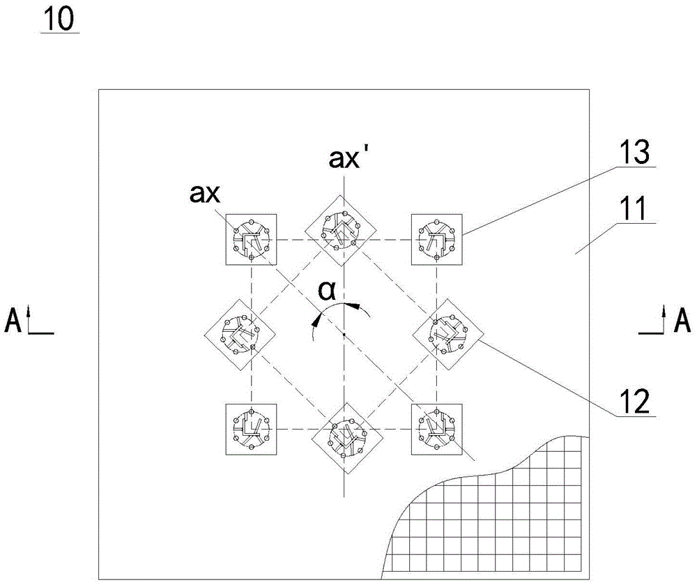
[0026] Example 1: Combining figure 1 and figure 2 Illustrate the composite tower crane foundation 10 of the present invention. In this embodiment, the tower cranes (not shown) whose models are ST5513 and ST6015 are taken as examples. The distance between two adjacent legs. The composite tower crane foundation 10 includes a concrete foundation 11 arranged on the ground; two sets of pre-embedded components anchored in the concrete foundation 11 are respectively a pre-embedded component 12 corresponding to the tower crane one (ST5513), and a The second embedded component 13 corresponding to the second tower crane (ST6015); each set of embedded components 12, 13 includes four embedded parts 17 that can be connected to the four foot bolts of the corresponding tower crane body, and the embedded component one 12 and the embedded part 17 of embedded assembly two 13 are arranged alternately. The reinforcement in the above-mentioned concrete foundation 11 is a double-layer two-way s...
Embodiment 2
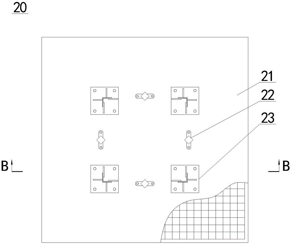
[0032] Embodiment 2: Combination image 3 and Figure 4 The composite tower crane foundation 20 of the present invention is different from the first embodiment in that the concrete foundation 21 of the present embodiment is provided with two sets of embedded components 22, 23, which are similar to the tower cranes whose models are QTZ80 and STL230 respectively. Correspondingly, the embedded part 24 is a cylinder vertically arranged in the concrete foundation 21. The bottom end of the cylinder is in the shape of a truncated cone, and the end with a larger outer diameter at the bottom of the embedded part 24 is close to the bottom surface of the concrete foundation 21. , the top of the embedded part 24 is connected with the foot bolts of the tower body. The above-mentioned embedded parts 24 are firmly embedded in the concrete foundation 1, and are non-detachable embedded parts. Compared with the embedded parts in the first embodiment above, the structure of the embedded parts in ...
Embodiment 3
[0033] Example Three: Combining figure 1 and figure 2 Illustrate the construction method of the composite tower crane foundation of embodiment one, concrete steps are as follows:
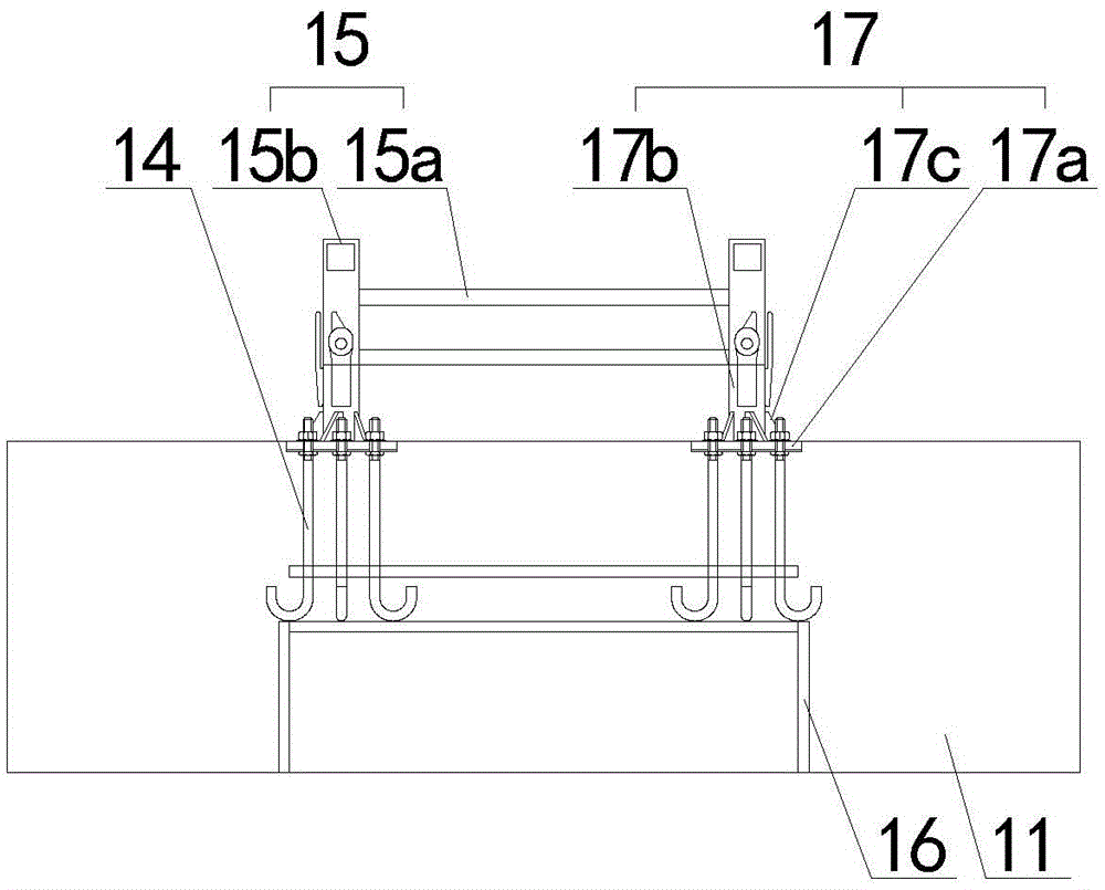
[0034] 1. Erection of the reinforcement cage and formwork (not shown in the figure) in the concrete foundation 11 to be poured. The reinforcement cage is composed of double-layer two-way reinforcement mesh sheets, and a pre-embedded component 12 and a number of pre-embedded bolts 14 are arranged in the reinforcement cage , and the pre-embedded component 12 and the pre-embedded bolt 14 are welded and fixed with the reinforcement cage;
[0035] 2. Connect the four embedded parts bolts of the embedded component 2 13 to the plane positioning frame 15, and a number of embedded bolts 14 are fixed to the embedded parts, and the plane positioning frame 15 connected with the embedded component 2 13 is inserted into the Reinforcement cage, and the embedded parts of the embedded component 12 and the embedde...
PUM
 Abstract
Description
Claims
Application Information
 - R&D Engineer
- R&D Manager
- IP Professional
- Industry Leading Data Capabilities
- Powerful AI technology
- Patent DNA Extraction
Browse by: Latest US Patents, China's latest patents, Technical Efficacy Thesaurus, Application Domain, Technology Topic, Popular Technical Reports.
© 2024 PatSnap. All rights reserved.Legal|Privacy policy|Modern Slavery Act Transparency Statement|Sitemap|About US| Contact US: help@patsnap.com