
Grooving machine and routing device

A technology of slotting machine and mounting plate, which is applied in the direction of milling machine equipment, milling machine equipment details, metal processing equipment, etc., and can solve the problems of fixed groove depth and difficult adjustment of groove spacing, etc.

Active Publication Date: 2016-05-04
TIANJIN CHENBAO ELECTROMECHANICAL TECH CO LTD
View PDF8 Cites 4 Cited by
  • Summary
  • Abstract
  • Description
  • Claims
  • Application Information

AI Technical Summary

Problems solved by technology

[0003] The object of the present invention is to provide a slotting machine and a routing and milling device to solve the technical problems in the prior art that the slots produced by the slotting machine are fixed in shape, and the depth and slot spacing are not easy to adjust

Method used


Image

  • Grooving machine and routing device
  • Grooving machine and routing device

Examples


Embodiment Construction

[0032] The technical solutions of the present invention will be clearly and completely described below in conjunction with the accompanying drawings. Apparently, the described embodiments are some of the embodiments of the present invention, but not all of them. Based on the embodiments of the present invention, all other embodiments obtained by persons of ordinary skill in the art without making creative efforts belong to the protection scope of the present invention.

[0033] In the description of the present invention, it should be noted that the terms "center", "upper", "lower", "left", "right", "vertical", "horizontal", "inner", "outer" etc. The indicated orientation or positional relationship is based on the orientation or positional relationship shown in the drawings, and is only for the convenience of describing the present invention and simplifying the description, rather than indicating or implying that the referred device or element must have a specific orientation, ...


PUM


Abstract

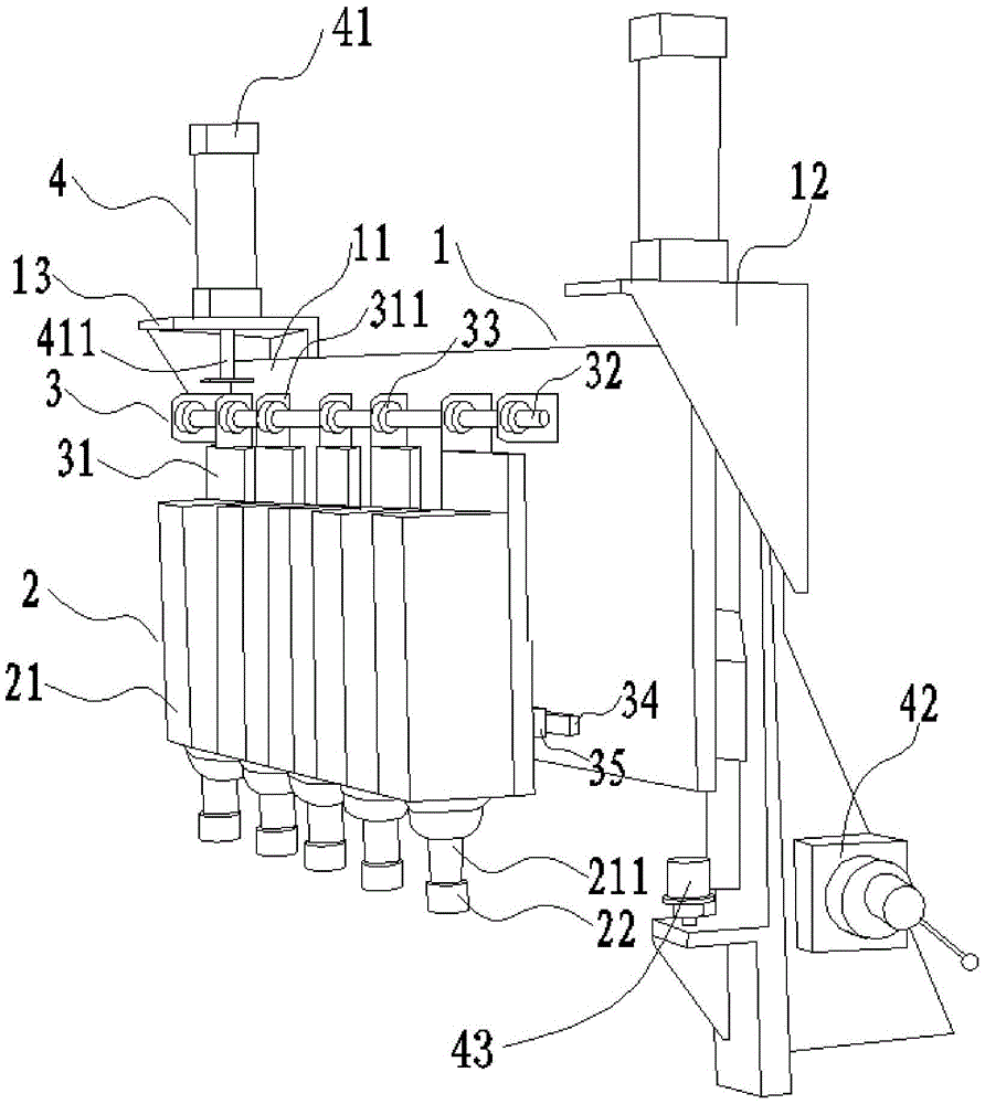
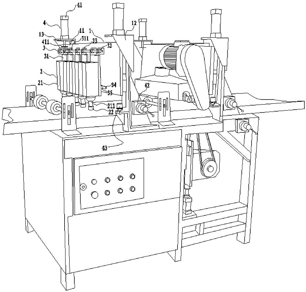
The invention provides a grooving machine and a routing device. The grooving machine comprises a support, a plurality of grooving units and a plurality of positioning units. The positioning units are all arranged on the support used for supporting and installing the grooving machine, and the grooving units are all arranged on the support through the corresponding positioning units. The positioning units comprise first positioning parts and second positioning parts, the first positioning parts are connected with the support and used for adjusting the horizontal distance between every two adjacent grooving units, and the grooving units are arranged on the first portioning parts through the second positioning parts used for adjusting the height of the grooving units. The routing device comprises a pre-milling machine, a plurality of pressing mechanisms, a rack and the grooving machine. The pre-milling machine, the pressing mechanisms and the grooving machine are all arranged on the rack, and the pre-milling machine and the grooving machine are arranged in sequence in the plate moving direction. The grooving machine solves the technical problems that in the prior art, the groove type of grooves formed by a grooving machine is fixed, and the depth and groove pitch of the grooves are difficult to adjust.

Description

technical field [0001] The invention relates to the technical field of mechanical equipment, in particular to a slotting machine and a router and milling device. Background technique [0002] The depth and groove spacing of the dovetail grooves produced by the existing groovers are fixed, difficult to adjust, and difficult to meet different needs. And sometimes it is necessary to groove both sides of the plate, which is even more difficult to achieve, so a more flexible and multifunctional groover is needed. Contents of the invention [0003] The object of the present invention is to provide a slotting machine and a routing and milling device to solve the technical problems existing in the prior art that the slots produced by the slotting machine are fixed in shape, and the depth and slot spacing are not easy to adjust. [0004] The slotting machine provided by the present invention comprises: a bracket, a plurality of slotting units and a plurality of positioning units, ...

Claims


Application Information

Patent Timeline
IPC IPC(8): B23C3/28
CPCB23C3/28B23C2220/36
Inventor 刘浩峰
Owner TIANJIN CHENBAO ELECTROMECHANICAL TECH CO LTD
Learn More