A quick automobile sheet metal workbench
A technology for workbenches and automobiles, applied in metal processing equipment, manufacturing tools, feeding devices, etc., can solve the problems of large volume, time-consuming and laborious, slow lifting and positioning speed, etc.
- Summary
- Abstract
- Description
- Claims
- Application Information
AI Technical Summary
Problems solved by technology
Method used
Image
Examples
Embodiment 1
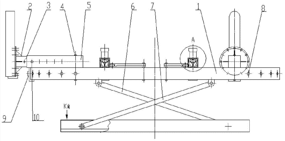
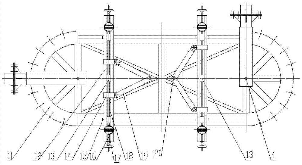
[0056] like figure 1 , figure 2 Shown, a kind of shortcut automobile sheet metal workbench comprises main supporting platform 1, and main supporting platform 1 is provided with transverse supporting beam 12, and transverse supporting beam 12 can move laterally along main supporting platform 1 through triangular fixed frame structure, and laterally The two ends of the support beam 12 are provided with clamping module groups 17, and the clamping module groups 17 are driven by the clamping module group moving screw 16 to move longitudinally along the transverse support beam 12 and can rotate horizontally. The module group 17 realizes movement switching through a spline structure, and the lower part of the clamping module group 17 is also provided with a locking device.
[0057] The further optimized technical solution of the present invention is that the triangular fixed frame structure includes a center pin 20, the center pin 20 is fixed on the main support platform 1, the sl...
Embodiment 2
[0086] A quick-type automobile sheet metal workbench, different from Embodiment 1, is that the center of the semi-arc surface 11 of the main support platform is provided with a horizontal rotating arm pin 4, and the horizontal rotating arm 5 can rotate around the horizontal rotating arm pin 4 in the horizontal direction. And determine the position on the horizontal plane by the horizontal rotation positioning pin 9 and the horizontal rotation positioning hole 8.
Embodiment 3
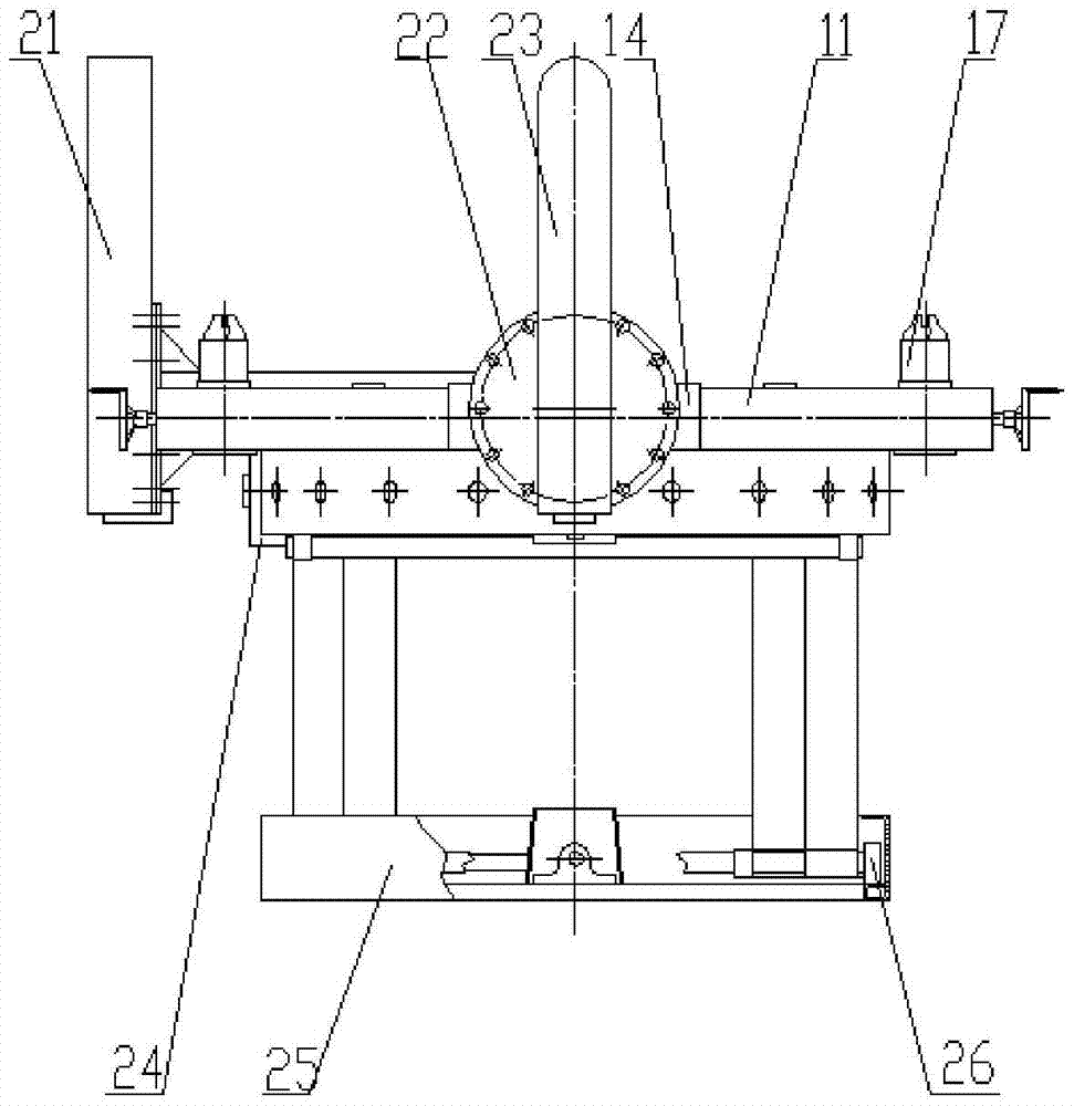
[0088] A quick-type automobile sheet metal workbench is different from Embodiment 2 in that the stretching arm A23 and the stretching arm B21 are symmetrically arranged on the semicircular surface 11 of the main support platform 1 at both ends of the main support platform 1 . The stretching arm A23 and the stretching arm B21 can horizontally rotate and be positioned around the semi-arc surface 11 of the main support platform through the horizontal rotating arm 5 .
PUM
 Abstract
Description
Claims
Application Information
 - R&D
- Intellectual Property
- Life Sciences
- Materials
- Tech Scout
- Unparalleled Data Quality
- Higher Quality Content
- 60% Fewer Hallucinations
Browse by: Latest US Patents, China's latest patents, Technical Efficacy Thesaurus, Application Domain, Technology Topic, Popular Technical Reports.
© 2025 PatSnap. All rights reserved.Legal|Privacy policy|Modern Slavery Act Transparency Statement|Sitemap|About US| Contact US: help@patsnap.com


